Week 9-Creation of 1D Connectors Challenge
Aim:- Creation of 1D connectors.
Objective:-
* Check the element and ensure the given midsurface is proper.
* Mesh the given model as per given quality criteria.
* Create connector and Attach the various parts of the given model
1. Right_Rail_2 & Front_truss_1:- Seam-Quad(angled+capped+L)
2. Left_Rail_2 & Front_truss_1:- Quad elements
3. Front_truss_2, Front_truss_1 & Right_Rail_1:- Spot weld with 2 Layers and 5 mm Diameter
4. Front_truss_2, Front_truss_1 & Left_Rail_1:- Hexa (Adhesive)
5. Rear_truss_2 & Right_Rail_2:- Bolt Connector
6. Rear_truss_2 & Left_Rail_2:- Bolt Connector
7. Right_Rail_1 & Right_Rail_2:- Spot-weld with Rigid Elements
8. Left_Rail_1 & Left_Rail_2:- Spot-weld with Spring Elements
9. Rest all the component left Join them with suitable connectors
Procedure:-
1. Import the model:
* First we import the model in hypermesh.
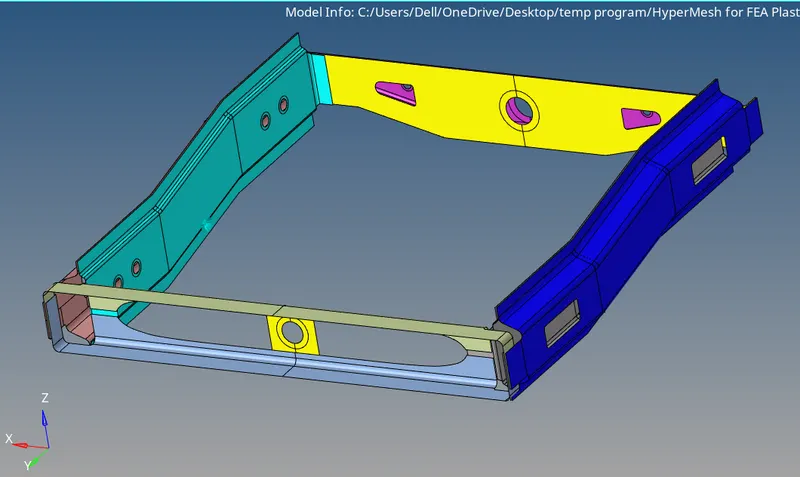
2. Geometry cleanup and Meshing:
* After the importing the model we have to check the geometry and do geometry cleanup with different tools such as quick edit tools surface edit tools, etc.
* When cleanup is done we setup the quality criteria file which is given in challenge.
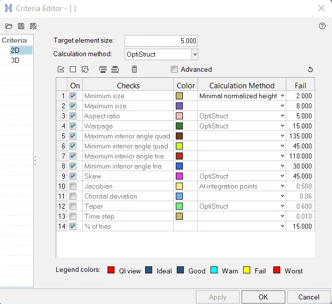
* Ones we set the criteria file we go for automeshing.
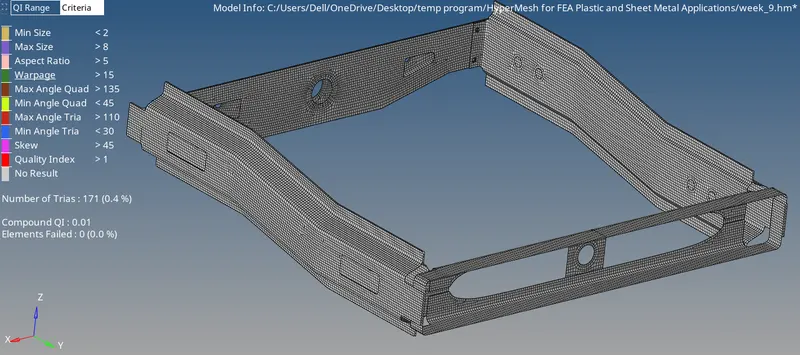
* For 2D meshing we use automesh tool and mesh the whole geometry.(2D - automesh - size and bias)
* After meshing we check the elements which are failing for quality concern.
* We have to clean this failed elements with some tools such as rebulid , quality index panel , remesh ,etc and clear all failed elements.
3. Mdelling of Connectors
* Create the connectors on the components as per given instructions.
1. Right_Rail_2 & Front_truss_1:- Seam-Quad(angled+capped+L)
* Isolate the Right_Rail_2 & Front_truss_1.
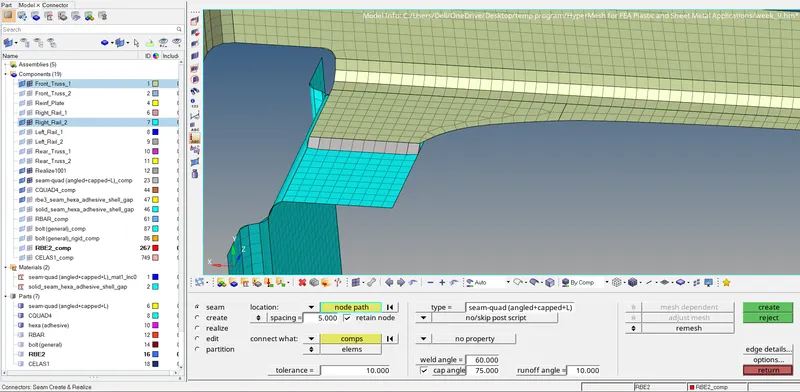
* Select 1D - Connector - Seam option.
* Select the type as 'Seam - quad ( angle+capped+L)'.
* Now select the location where the connector needs to be created by clicking node list.
* Specify the spacing value as 5 ( since element size is 5) and select the 'comp' option under connect what in order to create the connector between those two component.
* Give the tolerance value based on the distance between the two components.
* Before click on create button we click right side box and select remesh option so we get better element after the seam connection process.
* Click on create button to create the connector. the component is connected as shown in below image.
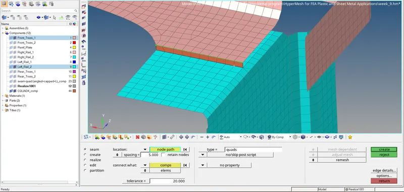
2. Left_Rail_2 & Front_truss_1:- Quad elements
* Isolate the Left_Rail_2 & Front_truss_1
* Select 1D - Connector - Seam option.
* Select the type as 'Seam - quad'.
* Now select the location where the connector needs to be created by clicking node list.
* Specify the spacing value as 5 ( since element size is 5) and select the 'comp' option under connect what in order to create the connector between those two component.
* Give the tolerance value based on the distance between the two components.
* Before click on create button we click right side box and select remesh option so we get better element after the seam connection process.
* Click on create button to create the connector. the component is connected as shown in below image.
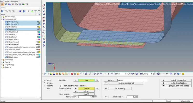
3. Front_truss_2, Front_truss_1 & Right_Rail_1:- Spot weld with 2 Layers and 5 mm Diameter
* Isolate the Front_truss_2, Front_truss_1 & Right_Rail_1.
* Select 1D - Connector - Spot option.
* Select the type as 'Spot - weld'.
* Now select the location where the connector needs to be created by clicking node list.
* Specify the spacing value as 5 ( since element size is 5) and select the 'comp' option under connect what in order to create the connector between those two component.
* Specify the number of layers ( number of components) to be welded under ' num layers' option. In this case we create the connector in order to attach 3 components therefore number of layer is selected as 3.
* Give the tolerance value based on the distance between components.
* we give diameter as 5mm as per given instruction.
* Now Click on create button to create the connector. the 3 component is connected as shown in below image.
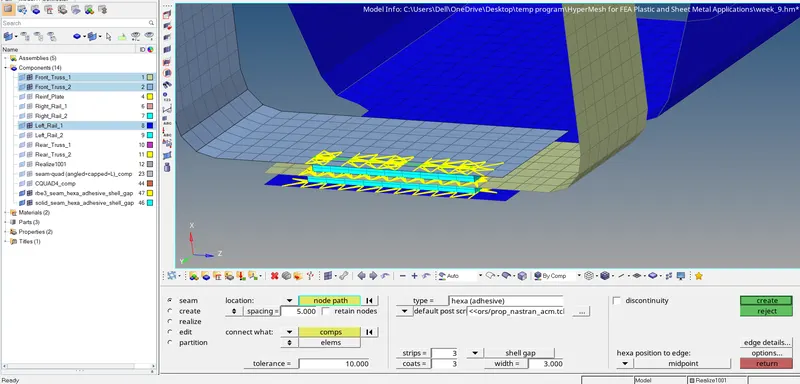
4. Front_truss_2, Front_truss_1 & Left_Rail_1:- Hexa (Adhesive)
* Isolate the Front_truss_2, Front_truss_1 & Left_Rail_1.
* Select 1D - Connector - Spot option.
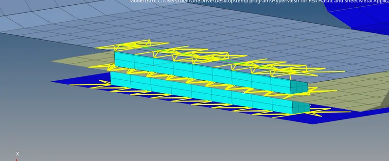
* Select the type as 'Seam - Hexa adhesive'.
* Now select the location where the connector needs to be created by clicking node list.
* Specify the spacing value as 5 ( since element size is 5) and select the 'comp' option under connect what in order to create the connector between those two component.
* Give the value of strips , coats and width as 3 in all.
* Give the tolerance value based on the distance between components.
* Now Click on create button to create the connector. the component is connected as shown in below image.
5. Rear_truss_2 & Right_Rail_2:- Bolt Connector
* Isolate the Rear_truss_2 & Right_Rail_2.
* Select 1D - Connector - Bolt option.
* Select the type as 'Bolt - Bolt (general)'.
* Now select the location where the connector needs to be created by clicking node.
* Give the tolerance value based on the distance between components.
* Give the number of layers to be bolted under 'num layer' option. In this case, since we have to attach two components therefore it should be 2.
* For bolt connection we required hole and since there is no hole present in the geometry so we have to select the option in right hand box as ' create if none' so we get hole for both if geometry does't have.
* Now Click on create button to create the connector. the component is connected through bolt as shown in below image.
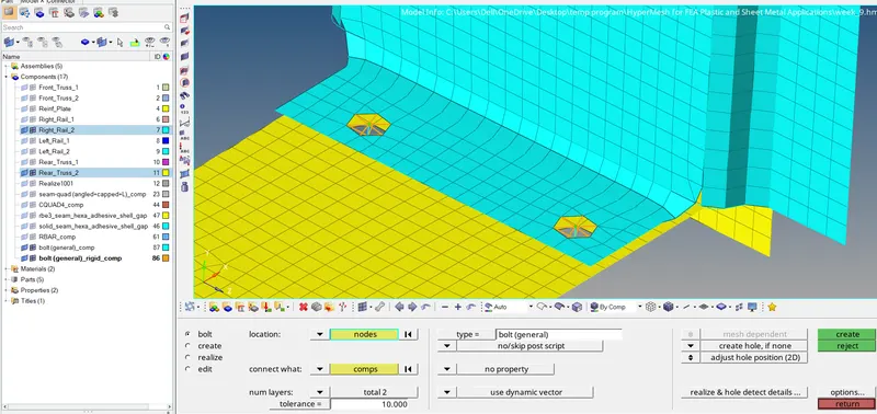
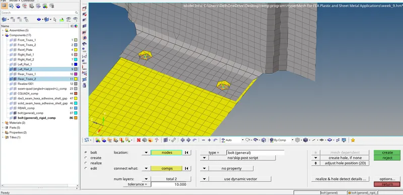
6. Rear_truss_2 & Left_Rail_2:- Bolt Connector
* These parts are also connected in same way as we done in point 6 task. the procedure for which is already discussed above.
* the components are connected as shown in below image.
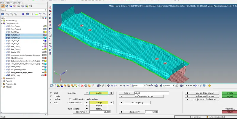
7. Right_Rail_1 & Right_Rail_2:- Spot-weld with Rigid Elements
* Isolate the Right_Rail_1 & Right_Rail_2.
* Select 1D - Connector - Spot option.
* Select the type as 'Spot - rigid element'.
* Now select the location where the connector needs to be created by clicking node list.
* Specify the spacing value as 5 ( since element size is 5) and select the 'comp' option under connect what in order to create the connector between those two component.
* Specify the number of layers ( number of components) to be welded under ' num layers' option. In this case we create the connector in order to attach components therefore number of layer is selected as 2.
* Give the tolerance value based on the distance between components.
* Now Click on create button to create the connector. the component is connected as shown in below image.
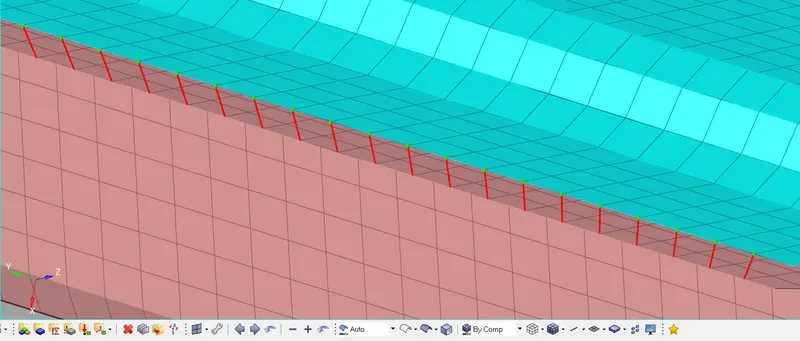
8. Left_Rail_1 & Left_Rail_2:- Spot-weld with Spring Elements
* Isolate the Left_Rail_1 & Left_Rail_2.
* Select 1D - Connector - Spot option.
* Select the type as 'Spot - Spring element'.
* Now select the location where the connector needs to be created by clicking node list.
* Specify the spacing value as 5 ( since element size is 5) and select the 'comp' option under connect what in order to create the connector between those two component.
* Specify the number of layers ( number of components) to be welded under ' num layers' option. In this case we create the connector in order to attach components therefore number of layer is selected as 2.
* Give the tolerance value based on the distance between components.
* Now Click on create button to create the connector. the component is connected as shown in below image.
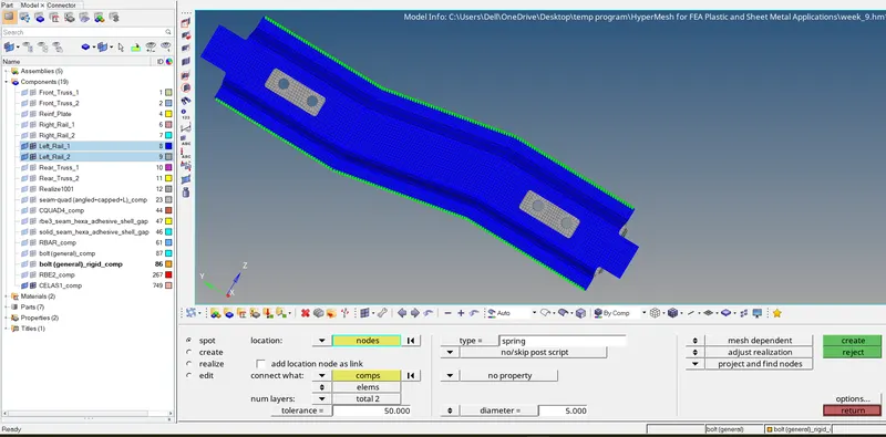
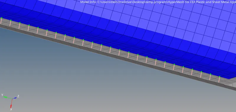
* Now we find which part is left such as rear truss 2 and rear truss 1 are connected with seam connector with rigid element and the reif plate is connected with the front truss 1 and fron truss 2 part by spot weld connectors.
* So in this way we connect all the given parts as shown in below figure.
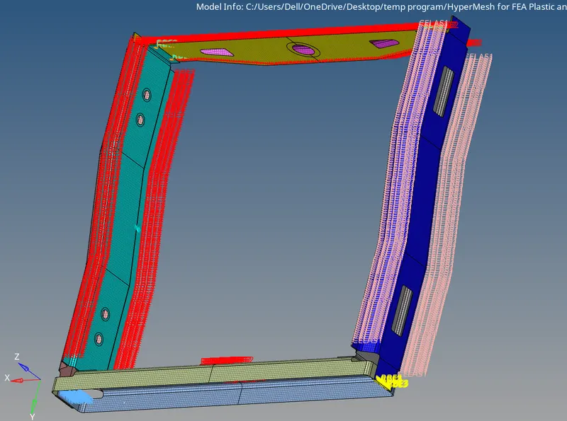
* Below image shows that different types of connectors used in this model.
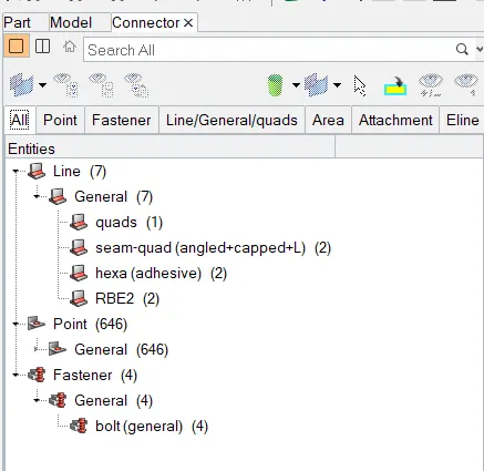
Conclusion:-
Hence we used different types of connectors in this challenge , thus i have learned how to connect the parts with the help of connectors and uses of connectors in Hypermesh.