Week 9-Creation of 1D Connectors Challenge
Q.1) ANSWER –
OBJECTIVE – TO MESH THE GIVEN COMPONENTS AND ATTACH THEM USING SPECIFIC CONNECTORS.
PROCEDURE
FIRST PHASE OF THE COMPONENT
1.1) First, we import the given model [Command – Import<Import Model<Select the file to be imported<And click on import] [REFER IMG 1] 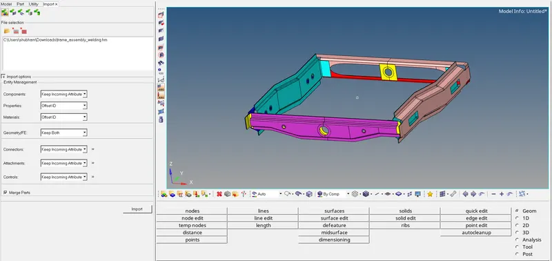
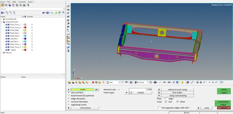
1.2) After the model is imported, we mesh the component. [2D<automesh<target element size =5<and click on mesh] [REFER IMG 2]
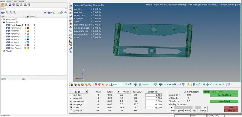
1.3) After the components are meshed, we check if any elements are failing the given quality criterions. [REFER IMG 3]
SECOND PHASE OF THE COMPONENT -Now we attach the components using the connectors.
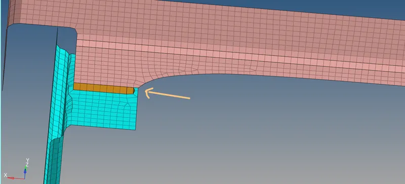
2) Right Rail 2 & Front Truss 1: - Seam-Quad(angled+capped+L)
2.1) We have to connect the following components using the given connector. First, we isolate the two components.
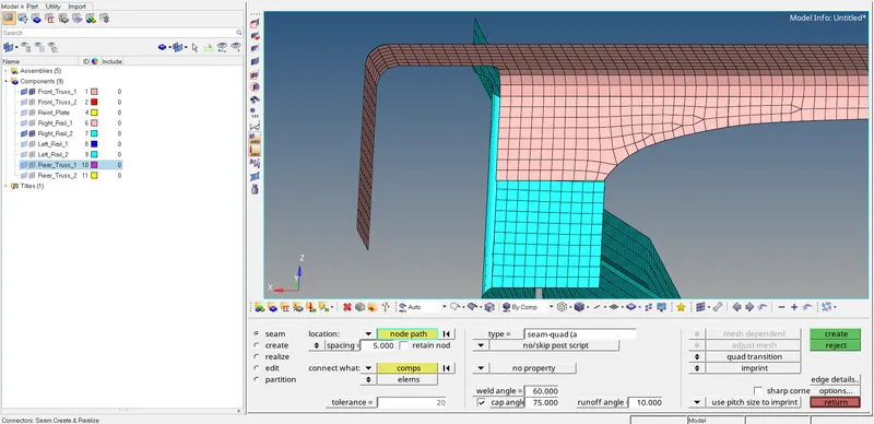
2.2) Now we select the connectors. [Command<2D<Connectors<Seam] [REFER IMG 4]

The location option helps us to know which nodes are selected to connect the two components.
Next, we select the type of seam = Seam-Quad(angled+capped+L)
Tolerance can be varied depending on the components.
2.3) Now we have successfully created a connector between the components and made sure that all of them are realised. [REFER IMG 5 & IMG 6]
3) Left Rail 2 & Front Truss 1: - Quad elements
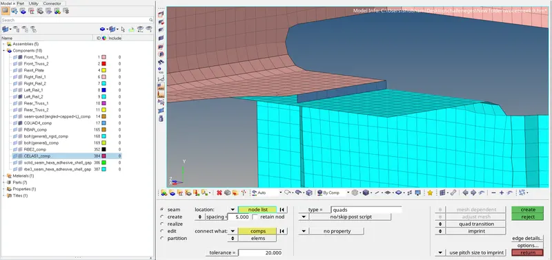
3.1) The same above process is followed of isolating the components and then selecting the nodes to be connected. [Command< 2D<Connectors< Seam< Quads] [REFER IMG 7]
4) Front_truss_2, Front_truss_1 & Right_Rail_1: - Spot weld with 2 Layers and 5 mm Diameter
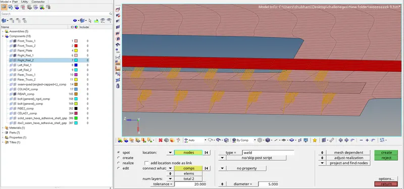
4.1) Again we isolate the particular components. We have to connect them with the spot weld connectors [ Command<2D<Connectors<Spot] [REFER IMG 8]

4.2) After selecting the nodes, tolerance and assigning the diameter we click on create and the connection has been made. [REFER IMG 9]
5. Front_truss_2, Front_truss_1 & Left_Rail_1: - Hexa (Adhesive)
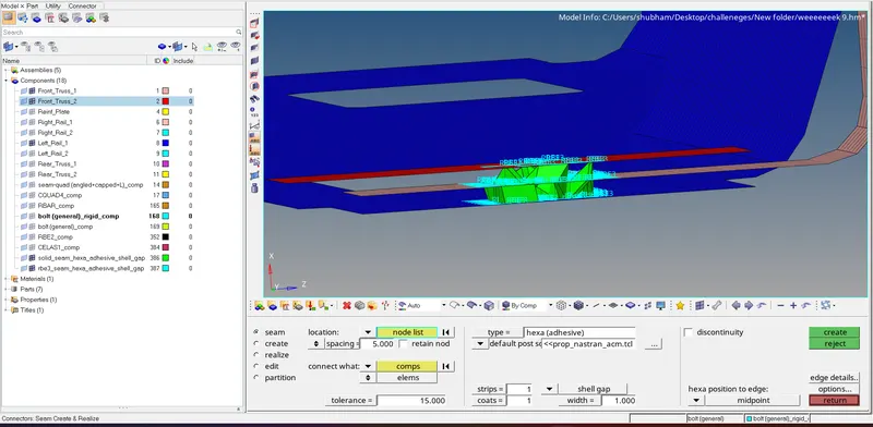
5.1) Again we follow the same process of isolating the particular components. We have to connect them with the seam hexa(adhesive) connectors. [ Command<2D<Connectors<hexa (adhesive)] [REFER IMG 10]

5.2) After selecting the nodes, spacing and tolerance we click on create and the connection is made. [REFER IMG 11]
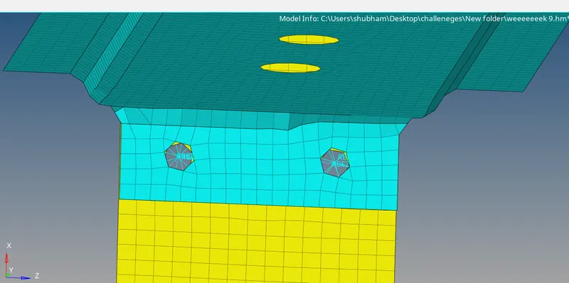
6. Rear_truss_2 & Right_Rail_2 AND Rear_truss_2 & Left_Rail_2: - Bolt Connector
6.1) We follow the same procedure of isolating the components and connect the components using bolt connector [ Command< 2D< connectors< bolt]. [REFER IMG 12]

6.2) After selecting the nodes for connecting the components and giving the tolerance we click on create. [REFER IMG 13]
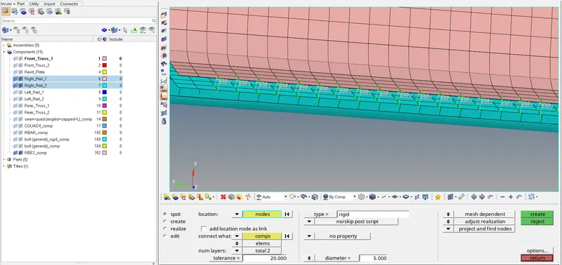
7.Right_Rail_1 & Right_Rail_2: - Spot-weld with Rigid Elements
7.1) We follow the same procedure of isolating the components and connect the components using spot weld connector. [ Command< 2D< connectors< spot<type=rigid] [REFER IMG 14]

7.2) After selecting the nodes, assigning the tolerance and diameter we click on create. [REFER IMG 15]
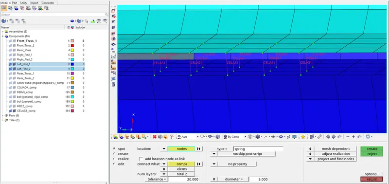
8.Left_Rail_1 & Left_Rail_2: - Spot-weld withSpring Elements
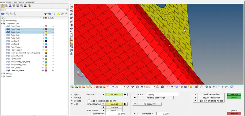
8.1) We follow the same procedure of isolating the components and connect the components using spot weld connector. [ Command< 2D< connectors<spot<type= spring] [REFER IMG 16]

8.2) After selecting the nodes, assigning the tolerance and diameter we click on create. [REFER IMG 17]
9.Rest all the component left Join them with suitable connectors
9.1) The remaining components are Rear_Truss_1 AND Reinf_Plate. We join them with spring elements
9.2) The Rear_Truss_1 is connected with Rear_Truss_2 [REFER IMG 18]
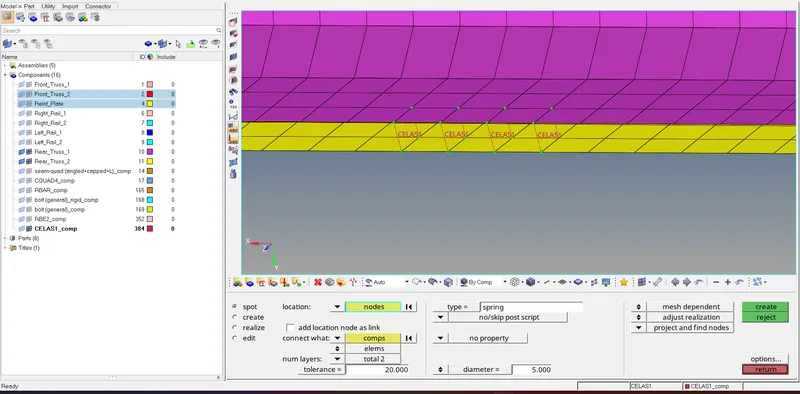
9.3) The Reinf_Plate is connected with Front_Truss_2 [REFER IMG 19]
CONCLUSION- ALL THE COMPONENTS ARE MESHED WITH NO ELEMENTS FAILING THE QUALITY CRITERIA AND ALL OF THEM ARE CONNECTED USING GIVEN AND SUITBALE CONNECTORS.