Week 12:Project 2-Meshing of Rear Wheel Holder challenge
Q.1) ANSWER-
OBJECTIVE- TO EXTRACT MIDSURFACE OF THE GIVEN COMPONENT AND TO PERFORM 2D MESH ACCORDING TO THE GIVEN QUALITY CRITERIONS.
PROCEDURE-
1.1) First we import the model. [Command- Import<Import Geometry<Select file type=IGES<and click on import]
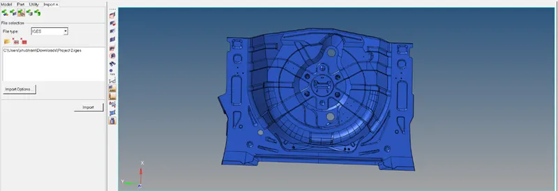
This is our imported model.
1.2) First we delete any solids present in the component since it is a 2D plastic model of varying thickness.
1.3) Now we proceed towards the midsurface extraction of the component.
[Command<Geometry<midsurface<automidsurface]
After the midsurface is extracted, we can see some geometrical errors which can be fixed manually by deleting the irregular or duplicate surfaces using the ‘FILLER SURF’ option or ‘DELETE’ option. Sometimes we can also use the RULED option in some cases or use the ‘SPLINE’ or ‘EXTEND’ option to extend or make the surface connected.
After cleaning all the geometric errors, we have to toggle the lines failing the quality criterions, we also need to fill the holes having diameter less than or equal to 5mm. After executing the following steps, the below model is good for meshing.
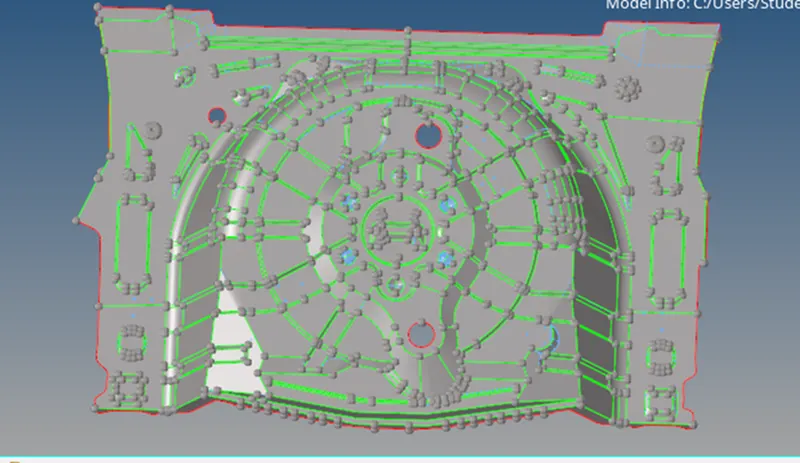
1.4) Now we start meshing the component according to the target element size= 5. [Command<2D<automesh<select the surfaces and click on mesh]
Before that we also set the criteria file settings.
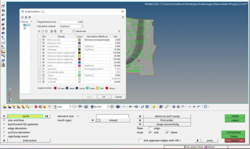
We mesh the component continuously until we get a result with low trias, low elements failing the quality criteria, having a proper mesh flow with no rotating quads. During meshing we set the meshing options preference as KEEP MESH rather than ADVANCED MESH because this option wouldn’t distort the meshing and the mesh quality when we have to defeature the surface.
Now to make node to node connection we can go to tools<edges and give equivalence by changing the tolerance value varying from 0.1 to 1. We also give the connection manually by using the replace option.
We also assign thickness to the model and enable the 2D Traditional and Detailed Element Representation shown as below.
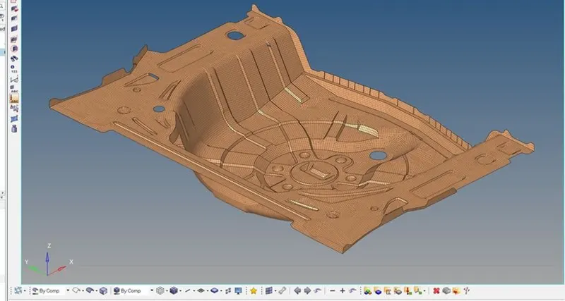
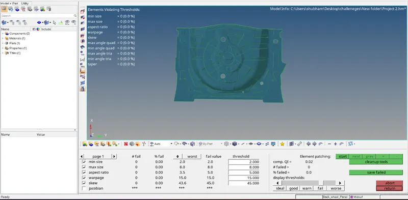
1.5) After we have done meshing there are still some elements failing the quality criterions. So, we rectify those elements using the element cleanup option or the cleanup tools in the quality index.
Finally, we get a component with no elements failing the quality criterions.
CONCLUSION- We got to know about the meshing in plastic component and how to segregate the midsurface of the same component. We also got to know how to defeature lines to get a proper good mesh flow.