Week 12:Project-1-Meshing of Door Inner Panel Challenge
Q.1) ANSWER –
OBJECTIVES - 1) TO EXTRACT THE MIDSURFACE OF THE COMPONENT.
2) TO MESH THE COMPONENT ACCORDING TO THE GIVEN CRITERIA’S.
3) TO ASSIGN THICKNESS TO THE COMPONENT.
PROCEDURE-
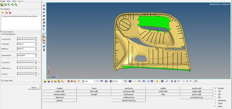
1.1) First we import the model. [Import<Import model<Select the file to be imported<click on import]
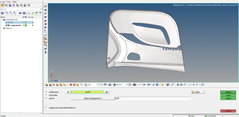
1.2) There are two different components in the model. Hence, we move one component to the other to avoid confusion. [Command<Tool<organize<Select the surface< Dest component= select the component where you want to move the surfaces<click on move]
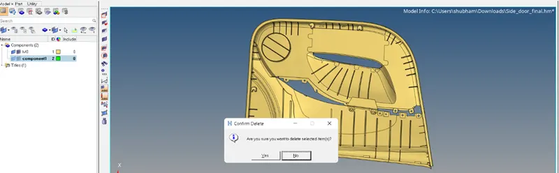
1.3) Now we delete the other component as it is empty.
1.4) Now we start extracting the midsurface. As the surface has varying thickness, we use the offset method or manual midsurfacing method to extract the midsurface of the component.
1.5) First we create a new component for our midsurface. We start by extracting surface by surface. [Command<Geometry<Surface edit<Offset].
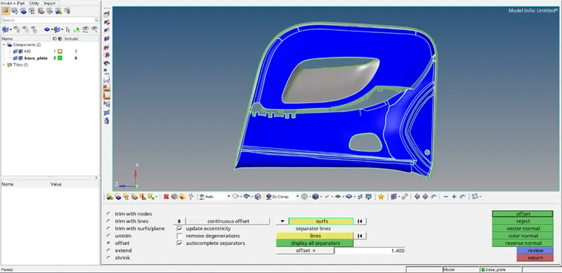
1.6) We also cleanup the geometrical errors as they occur.
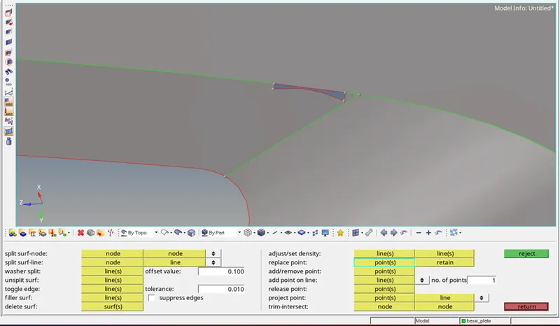
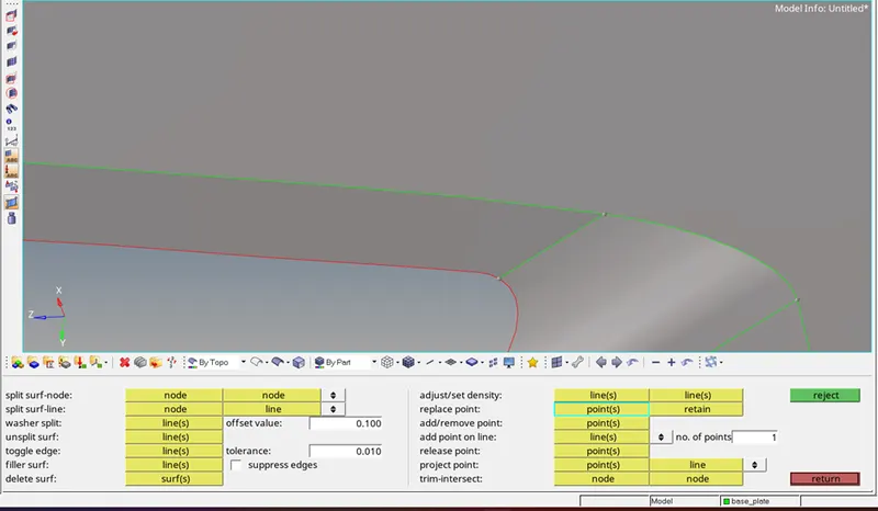
1.7) So now we have completed the midsurface extraction of one face of the component.
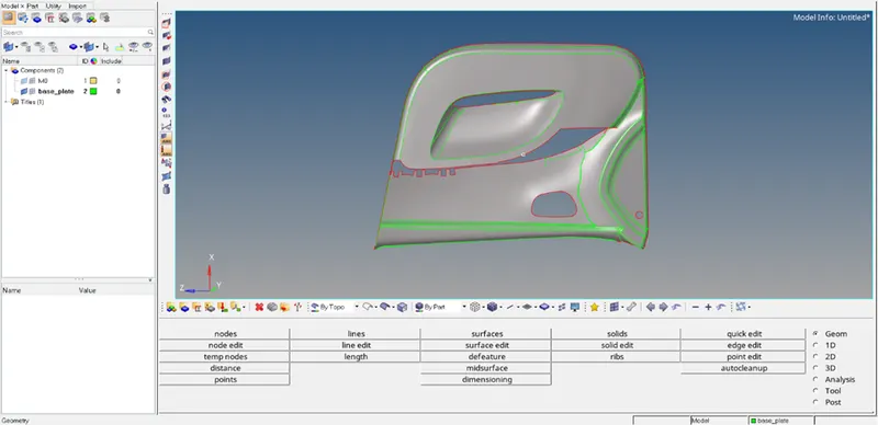
1.8) Now we move on to extract the ribs in the component.
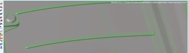
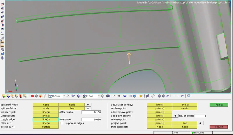
1.9) This is what the rib looks like. As we can see there is varying thickness hence, we use the following steps to extract its midsurface. So first we toggle the line between the rib. [Command<Geometry<quick edit<toggle edge]
1.10) After the line is toggled, we create a midline. [Command<Geometry<lines<Midline<and select the lines between which you want a midline]

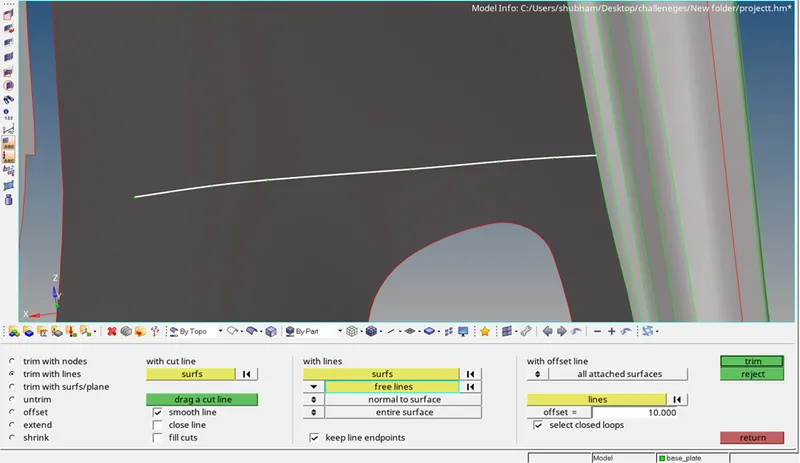
1.11) Now we trim the midline with the surface. [Command< surface edit< trim with lines]
1.12) After trimming the line, we join the lines to make a rib. [ Command<surfaces<ruled]
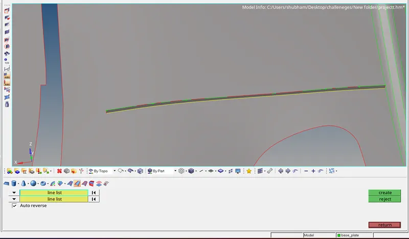
Hence a rib is successfully created.
And we follow this same procedure for all the similar ribs.
1.13) Now for this particular rib we can use the final edit tool options to extract the midsurface. [Command< Geometry< midsurface<final edit tools]
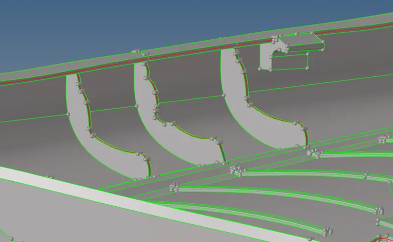
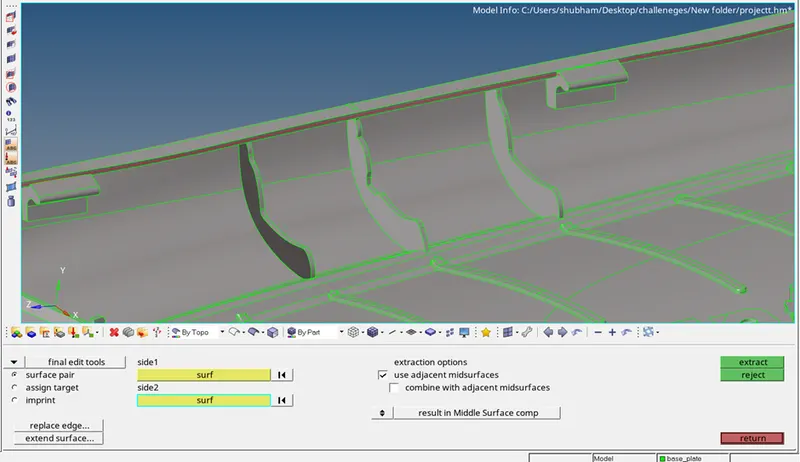
This is how the extracted rib looks like.
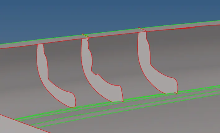
1.14) Now this rib is not attached to the base plate. Hence, we need to attach it using the extend option.
Before that we remove unnecessary points on the rib which might distort the geometry.
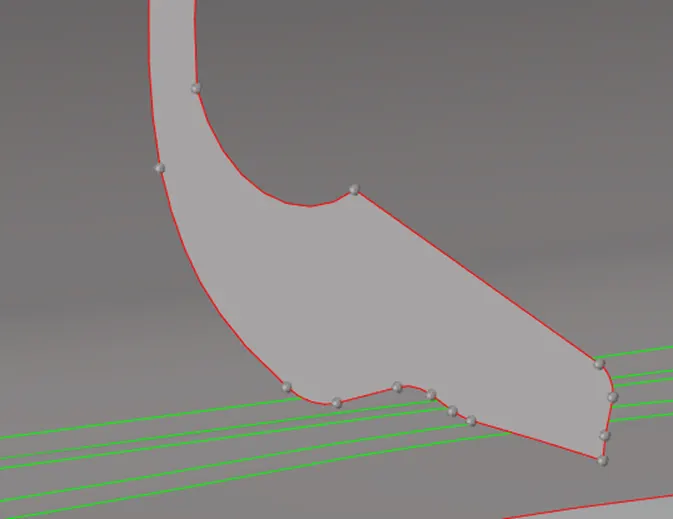
We remove these points by using quick edit tools.
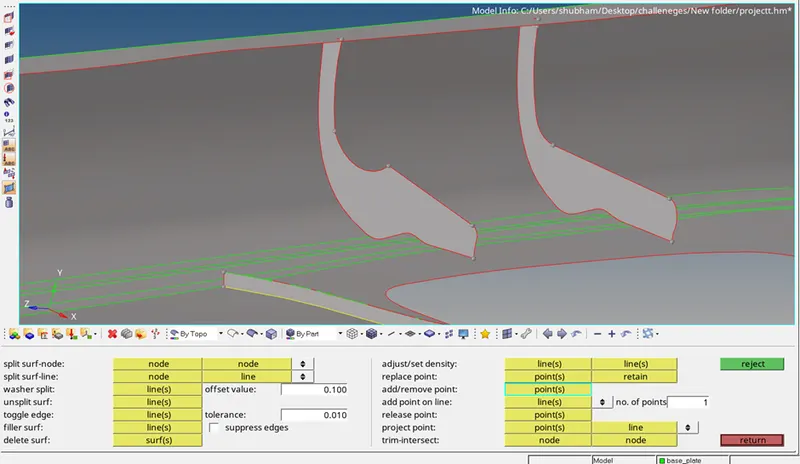
Now we use the extend option. [Command< Geometry<surface edit<extend].
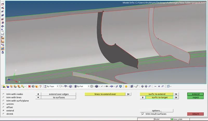
So, this is how the extended or attached rib looks like. And we follow this same procedure for similar ribs.
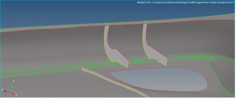
1.15) Now for this particular section we do the following steps.
First, we create a centre node between the circle, using Arc Centre option. [Command<Geometry<nodes<Arc Centre]
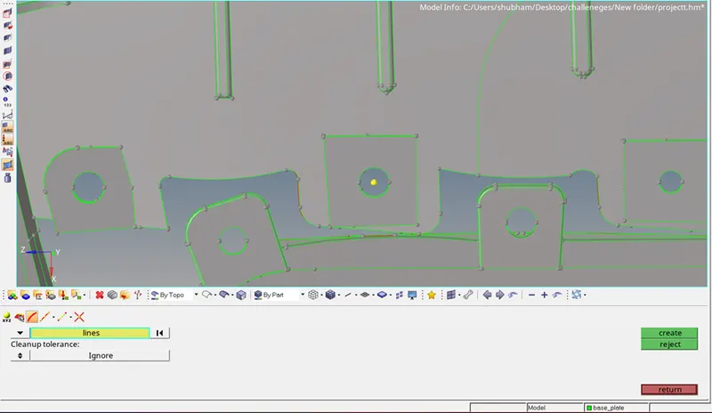
1.16)After the centre node is created, we create a surface using ruled option in the current component. [Command< Geometry<Surfaces<Ruled]
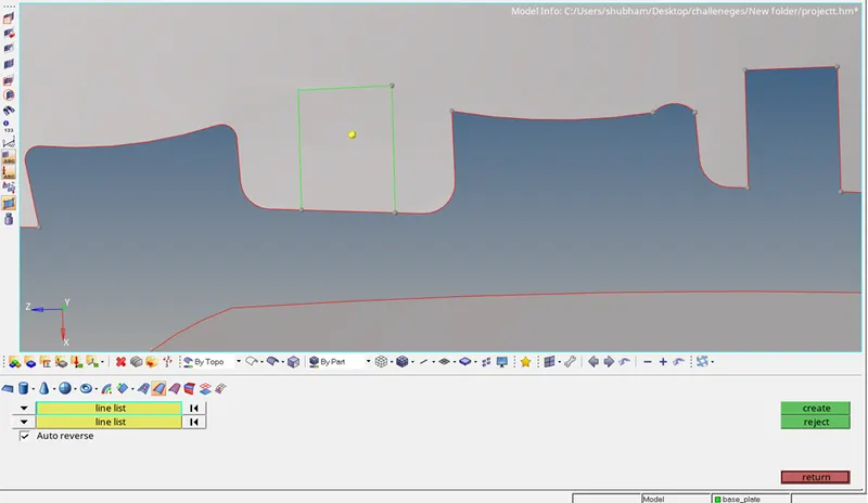
1.17) After the surface is created, we project the node to the surface. [Command<tool<project] OR [Command< SHIFT+F7]
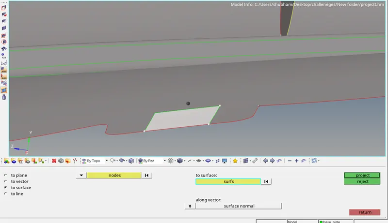
1.18) After the node is projected on the surface, we create a circle. [Command<Geometry<lines<Circle centre and radius]
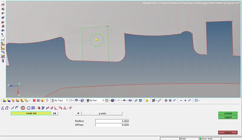
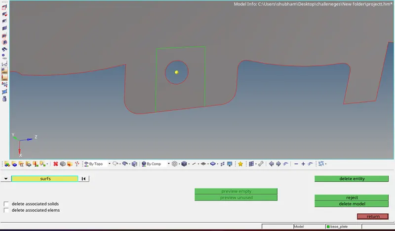
1.19) Now we delete the inner surface .
1.20) Now for this particular rib we again use the offset method and we follow the same steps which we followed for the ribs in the previous steps.
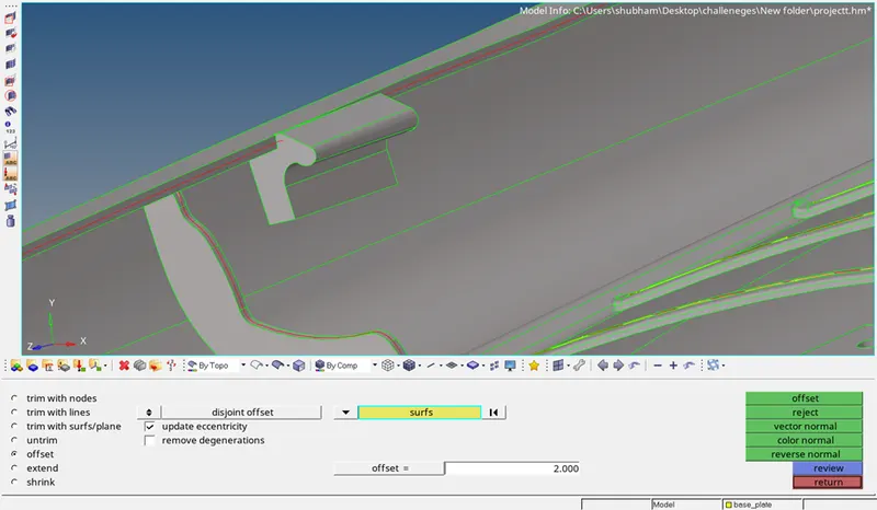
1.21) So this is how the offsetted surface looks like.
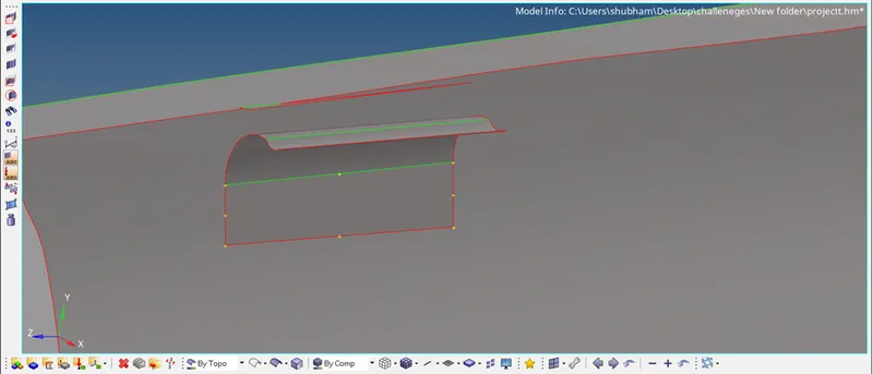
1.22) Now we have to extend the surface. So, we create lines on the surface edges. [Command<Extract edge<select the surfaces<and click on create]

1.23) Then we use the project tool to project it or extend it onto the surface.
[Command<Tool<Project]
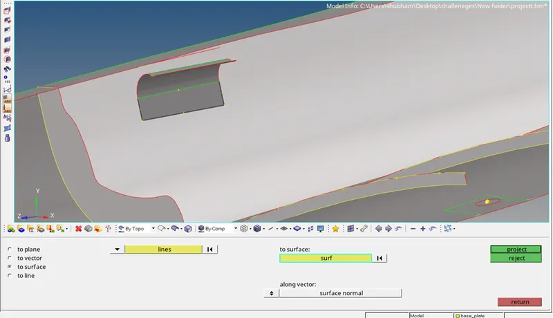
1.24) After projecting the lines, we create surfaces using ruled option. [Command<Surfaces<Ruled<select the lines<and click on create]
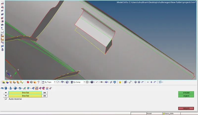
1.25) This is how the extracted midsurface component looks like.
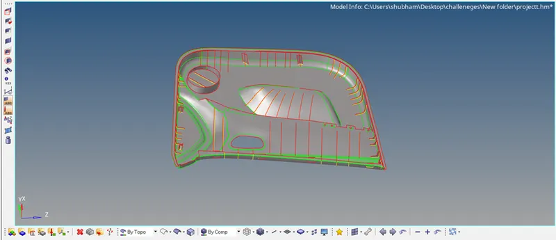
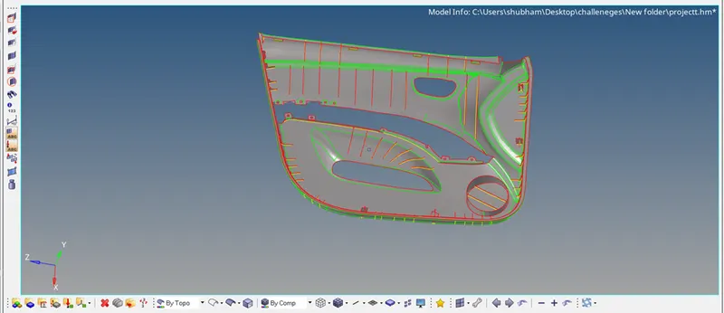
1.26) After the midsurface has been created for the component, we move on to mesh the component with the given quality criterions. But before automeshing the component we must set the quality criterions. [Command<Preferences<criteria file settings]
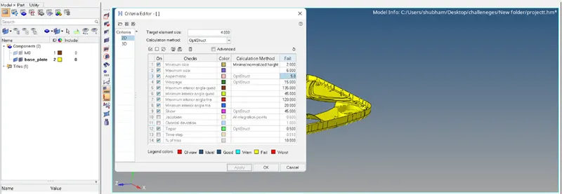
1.27) Now we mesh the component. [Command<2D<automesh<select the surfaces<element size=4<and click on mesh]

1.28) For the elements failing the quality criteria we use the cleanup tools or rebuild mesh option to rectify the failing elements, lower the percentage of trias and try to get a perfect mesh flow with no rotating quads or opposite trias.
The following image shows the component with no failing elements.
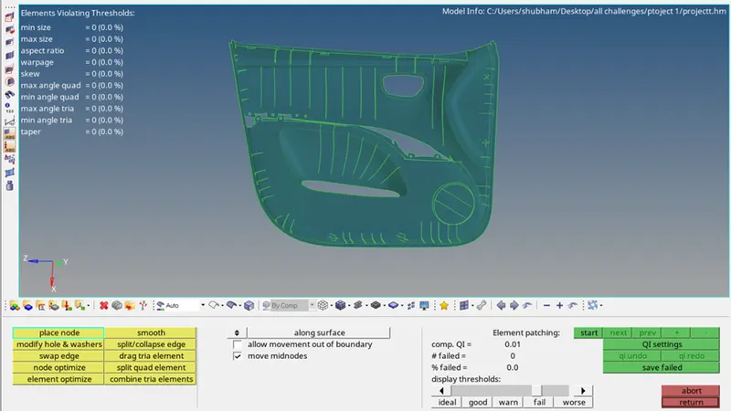
1.29) Now we assign thickness to the components.
First we create a new component and a new property. We assign the thickness in the property and assign the property to the component.
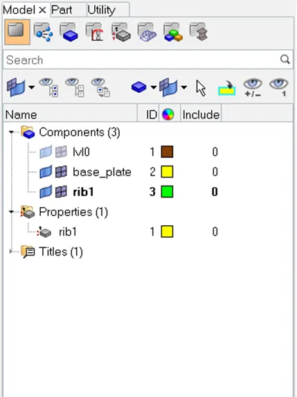
1.30After the component and property is created, we move the elements on the rib to the new component using the following command. [Command<Tool<Organise]]
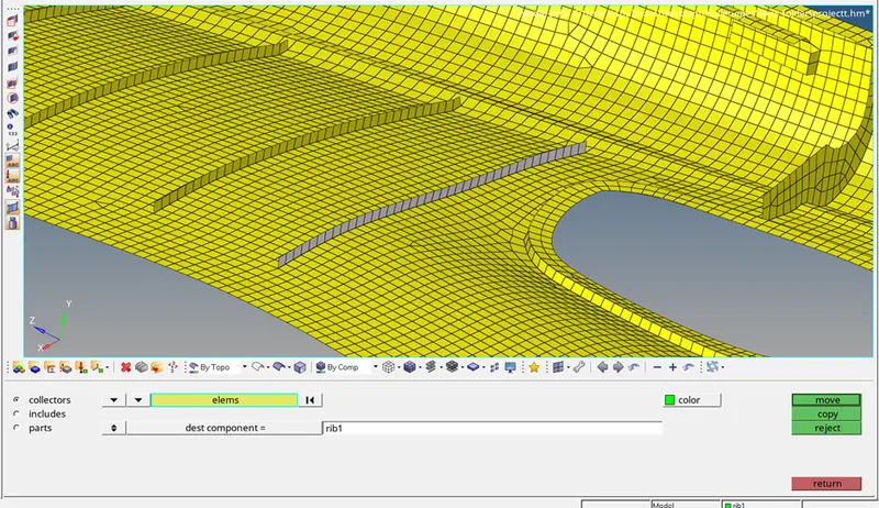
1.31) Now we measure the thickness of the rib and assign the thickness in the property. And then we assign this property to the component.
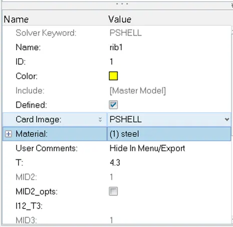
1.32) This is how the rib looks like with the assigned property in the 2D Detailed Element Representation.
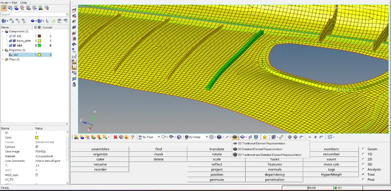
We do this same process for all the ribs.
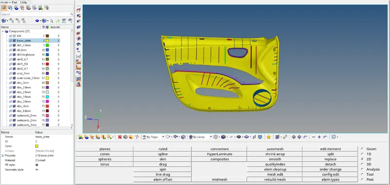
1.33) After assigning thickness and properties to all the components our procedure has been completed. This is how the components look in the 2D Detailed Element Representation.
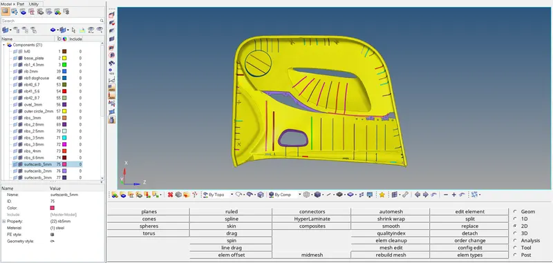
Conclusion- We successfully extracted the midsurface of the component, meshed it according to the given quality criterions and assigned thickness to all the components and ribs.