Week 9-Creation of 1D Connectors Challenge
Aim- To mesh the given geometry with the given quality criteria and create the connectors for various parts
Objective- To mesh the given component and create 1d connectors and join various parts with them
The quality criteria for the mesh
|
S.N |
Quality Criteria |
Value |
|
1 |
Aspect Ratio |
5 |
|
2 |
Skewness |
45 |
|
3 |
Warping |
15 |
|
4 |
Taper |
0.5 |
|
5 |
Min. Length |
2 Units |
|
6 |
Max. Length |
8 Units |
|
7 |
Min angle Quad |
45 |
|
8 |
Max angle Quad |
135 |
|
9 |
Min angle Tria |
30 |
|
10 |
Max angle Tria |
110 |
|
10 |
Tria % |
15 |
The following are the specification for the connectors
1. Right_Rail_2 & Front_truss_1:- Seam-Quad(angled+capped+L)
2. Left_Rail_2 & Front_truss_1:- Quad elements
3. Front_truss_2, Front_truss_1 & Right_Rail_1:- Spot weld with 2 Layers and 5 mm Diameter
4. Front_truss_2, Front_truss_1 & Left_Rail_1:- Hexa (Adhesive)
5. Rear_truss_2 & Right_Rail_2:- Bolt Connector
6. Rear_truss_2 & Left_Rail_2:- Bolt Connector
7. Right_Rail_1 & Right_Rail_2:- Spot-weld with Rigid Elements
8. Left_Rail_1 & Left_Rail_2:- Spot-weld with Spring Elements
Procedure-
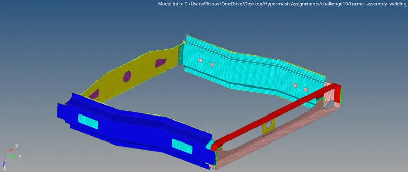
1. open the model
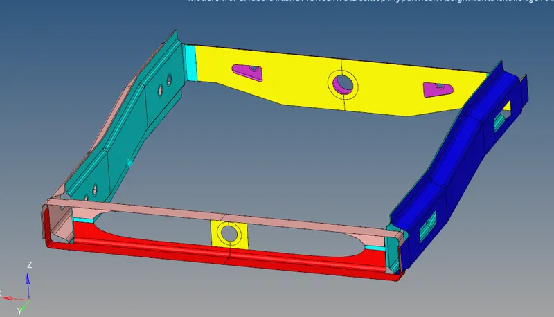
2. Do the 2d surface meshing for each component
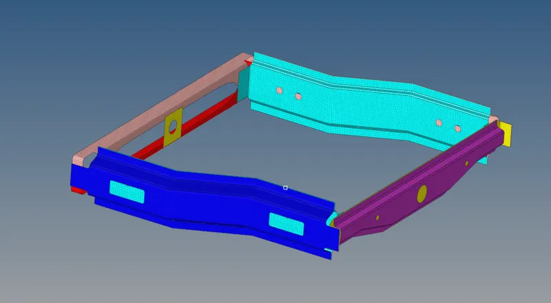
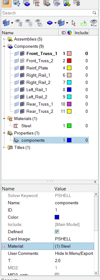
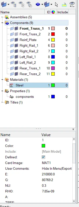
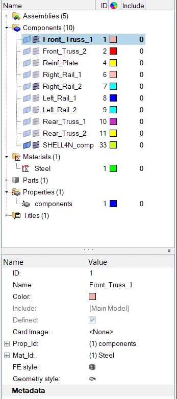
3. Create the material card set the properties and select the MAT1 and rename the card as steel, also create the property card set to the PSHELL element and rename it as components, set the thickness of to 2 units in the property card. Assign the material and property card to every component.
4. Creating the connectors
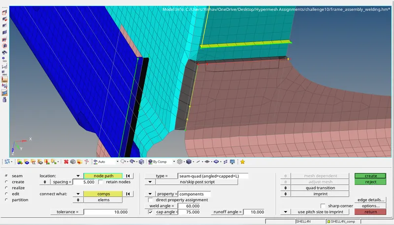
1. Seam-Quad(angled+capped+L)
for Right_Rail_2 & Front_truss_1
Go to 1d>connectors>seam
select the nodes by path
set the tolerance to 10 units
set the spacing to 5 units
in the weld type select angled+capped+L
set the weld angle to 60
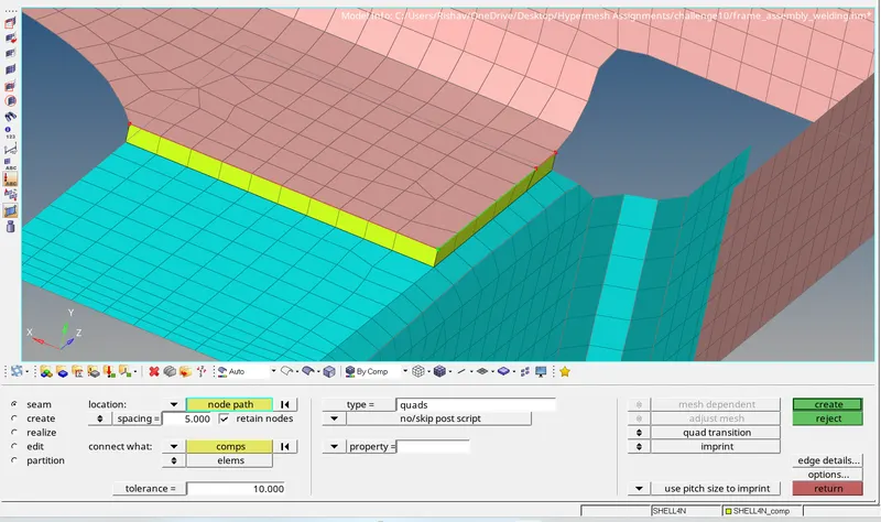
2. Quad elements
For Left_Rail_2 & Front_truss_1
Go to 1d>connectors>seam
select the nodes by path
set the tolerance to 10 units
set the spacing to 5 units
in the weld type select Quads
3.Spot weld with 2 Layers and 5 mm Diameter
Front_truss_2, Front_truss_1 & Right_Rail_1
Go to 2d > connectors > spot
Select the nodes where the weld is to be placed
select all the components
set the diameter value to 5 mm
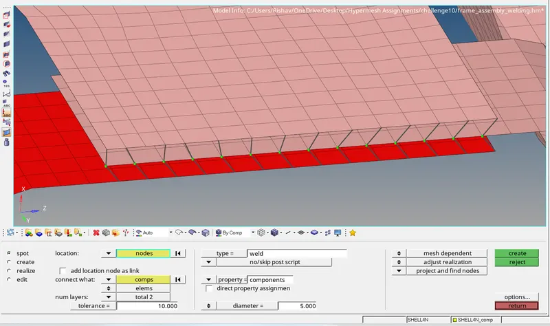
4. Hexa (Adhesive)
Front_truss_2, Front_truss_1 & Left_Rail_1
Go to 1d>connectors>seam
select the nodes by path
set the tolerance to 10 units
set the spacing to 5 units
in the weld type select Hexa(Adhesive)
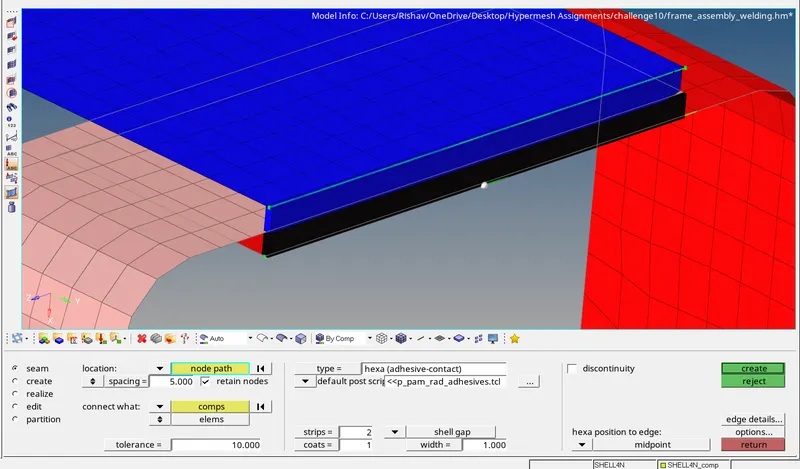
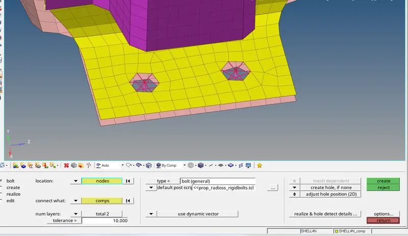
5. Bolt Connector
Rear_truss_2 & Right_Rail_2
Go to 1d> connectors> bolt
Select the nodes where the bolt be added
select create a hole if none
Select the 2 component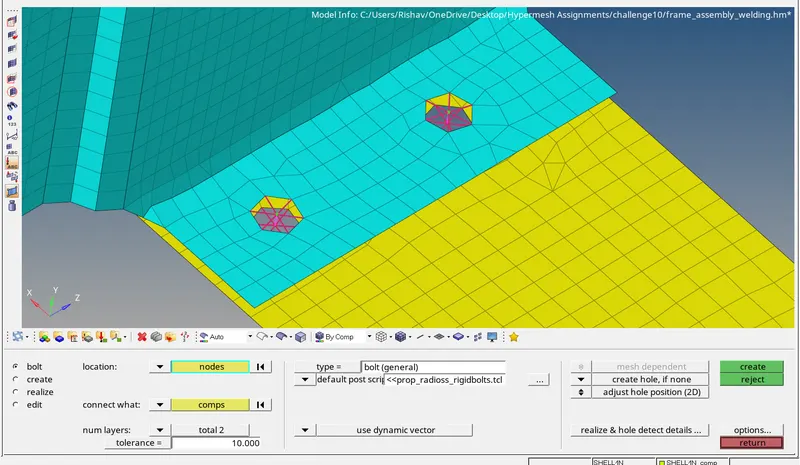 s
s
6. Bolt Connector
For Rear_truss_2 & Left_Rail_2
Go to 1d> connectors> bolt
Select the nodes where the bolt be added
select create a hole if none
Select the 2 component
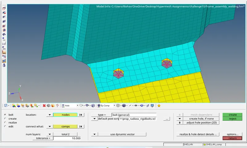
7.Spot-weld with Rigid Elements
For Right_Rail_1 & Right_Rail_2
Go to 1d> spotweld> select using nodes
select the bunch of nodes for the weld
select type to rigid elements
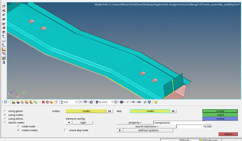
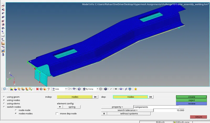
8. pot-weld with Spring Elements
For Left_Rail_1 & Left_Rail_2
Go to 1d> spotweld> select using nodes
select the bunch of nodes for the weld
select type to spring element
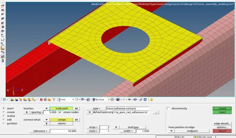
9.For rest of the components
for Front truss 1, front truss 2 and reinf plate join using the connectors hexa adhesive
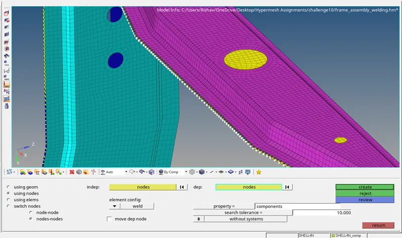
For Rear truss 1 and rear truss 2 join using the spot weld
For rear truss 2 and right rail 2 join using the bolt connector
Result
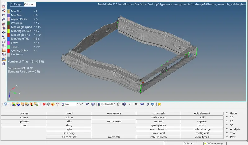
All the components are joined with the connectors with zero element failure
Conclusion-
Every component is meshed and joined using connectors with properly realizing it.