Week 9-Creation of 1D Connectors Challenge
AIM:
To mesh the given component with 5mm element size and then connect all the components with respective connectors of various specifications which are provided.
PROCEDURE:
CONNECTORS:
These are geometric entities used to create elements like spot welds, bolt, seam welds, adhesives, masses etc to the component. To put it in simple words, they represent how one component is related or linked or connected to each other such that this would provide the solver the required information about the component connections. Some of the commonly used connectors are weld(spot & seam), mass, adhesives, bolts etc.,
1. Firstly, Import the given model in the hypermesh window and then perform the geometry cleanup as usual. In this case, the components doesn't has any solids and it only has surface in which most of them were perfect. Certain bits of free edges has been toggled to make the surface of the components complete.
2. Now, go to 2D tab in the main menu and go to automesh. Here, select all the displayed surface, enter the element size as 5mm (as per the requirement), click on the element type to mixed (such that we can mostly avoid trias) and click on automesh to mesh the complete component with 5mm elements.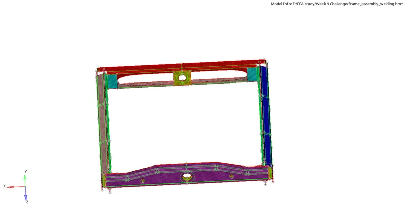
3. Now, to create all the connectors which are required,
i) Right_Rail_2 & Front_truss_1:- Seam-Quad(angled+capped+L)
To avoid confusion, open the Right rail 2 & Front truss 1 alone such that the place where it needs to be connected can be seen clearly. Now, go to 2D tab>>connectors>>Seam>> Node list (select the nodes in the edges of the component) >> spacing (5.00 since we've used element size 5mm) >> comps ( both the components) >> tolerance (10.00) >> type ( Quad (angled + capped + L) ) >> weld angle ( 45 to 60 usually) >> cap angle (75 default) & runff (10 default). In this case, Use quad transition >> Imprint. Such that the elements would be properly joined without any distortion in elements. Now, click create to create the seam weld.
If the connectors were in GREEN : Connector successful
If the connectors were in Yellow : Created but not realized
If the connectros were in RED : Failed
If there are any deviations and the connectors were failed or not realised, go to View >> Browser >> Hypermesh >> Connector
In order to use the connector tab, we should not be present in the 2D connectors option in the tools menu.
Now, Inside the connector tab we can see all the connectors which are created, right click on the specified connector and click on realize if the connectors were not realized,
If there arises a need to reverse the direction of the elements formed, click on the required connector inside the connector tab, scroll down and check into reverse direction option to reverse the direction of the connector.
This would complete the successful creation of the connector.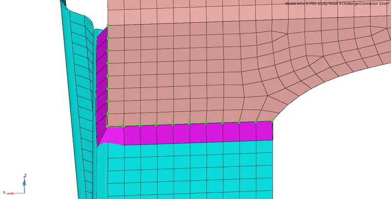
ii) Left_Rail_2 & Front_truss_1:- Quad elements
Keep the required components in view and then go to 2D tab >> connectors
Seam >> Node list ( select the nodes in the edges) >> spacing 5.00 >> Comps ( select the required components) >> tolerance ( 10.00) >> Type ( Quads ) >> no /skip post script >> no property >> Quad transition >> Imprint
Now, click on create to create quad element connector between the two required components.
If the elements formed were not equivalanced properly, we can use the equivalence option by clicking F3 and also, if the mesh seems distorted after the connectors were created, we can remesh certain elements to maintain the mesh quality parameters.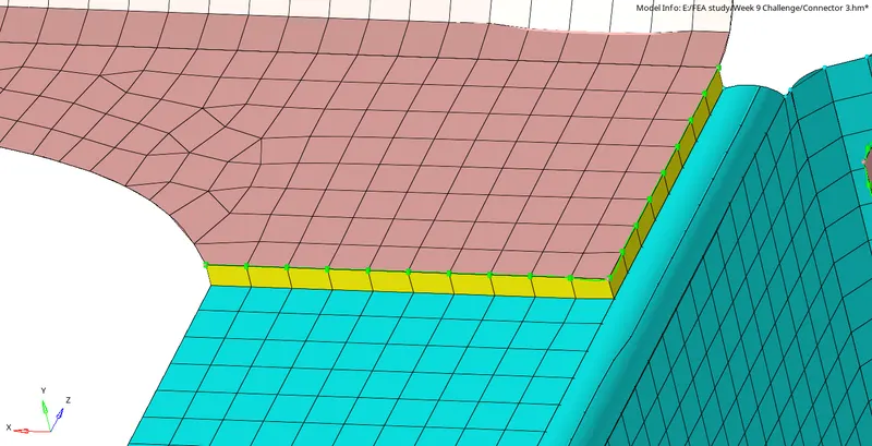
iii) Front_truss_2, Front_truss_1 & Right_Rail_1:- Spot weld with 3 Layers and 5 mm Diameter
Keep the required component alone in the graphics window, go to 2D >> connectors >> spot
Spot >> Node list (select the nodes in the edges of the components) >> comps ( select all the 3 components ) >> Num layers ( Total 3 - Required)>> tolerance (10.00) >> Type (Plot) >> No property >> no /skip post script >> Diameter (5.00 Required) >> mesh dependant >> adjust realization >> project and find nodes
Now, click on create to form the spot weld connector between these three components.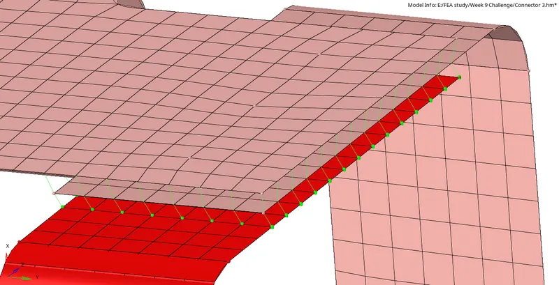
iv) Front_truss_2, Front_truss_1 & Left_Rail_1:- Hexa (Adhesive)
2D >> connectors >> Seam >> Node list ( select the nodes in the edges) >> spacing (5.00) >> Comps ( Select the top and the middle component ) since there are three layers, we need to connect one by one, so first select nodes of one component edges, select two components top and middle and proceed, then repeat the same for the middle and the lower component to connect all the three components. >> tolerance (10.00) >> Type ( Hexa adhesive ) >> Strips : 1, Coat : 1 >> Width default >> Create
Now, repeat the same steps by selecting the nodes from the bottom component and select the comps ( middle and the bottom component ) to create connectors between the middle and the bottom component. Now check for the connectivity and work with the equivalence option to rectify the errors if any, If needed, we can also remesh the certain elements which are distorted after the creation of connectors.
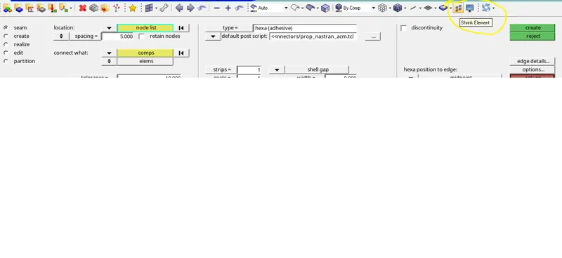
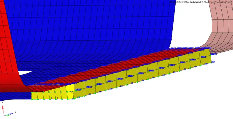
These connectors are prone to provoke duplicate elements. We can delete those by using SHRINK ELEMENT option to view all the elements individually (Exploded view ) such that the duplicate elements can be easily deleted.
Rear_truss_2 & Right_Rail_2:- Bolt Connector & vi) Rear_truss_2 & Left_Rail_2:- Bolt Connector
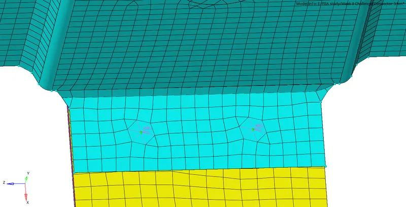
Keep the required geometry>> 2D >> connectors >> Bolt >> nodes ( select any node in the geometry to create bolt connection ) >> comps ( select both the components ) >> layers ( total 2 ) >> Tolerance (10.00) >> Type ( Bolt general ) >> Create hole, if none ( since there is no hole in the given component use this option else, use consider only existing hole ) >> adjust hole position 2D >> create.
Bolts has the tendency to distort the mesh quality, so after the bolt connection is made, we can remesh certain elements to maintain the mesh quality.
Repeat the same procedure for the other two components as well to create the bolt connection.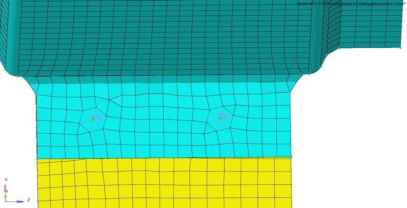
vii) Right_Rail_1 & Right_Rail_2:- Spot-weld with Rigid Elements
Keep the required components in the graphic window and the go to 2D>> Connectors >> Spot >> Node list ( select the nodes in the edge) >> Spacing (5.00) >> Comps ( Select both the component) >> Layers (2.0) >> Tolerance (10.00) >> Type ( rigid) >> Mesh dependant >> adjust realisation >> project and find nodes >> create
Now, If there are any errors in the connection, we can use equivalence option to connect the elements perfectly.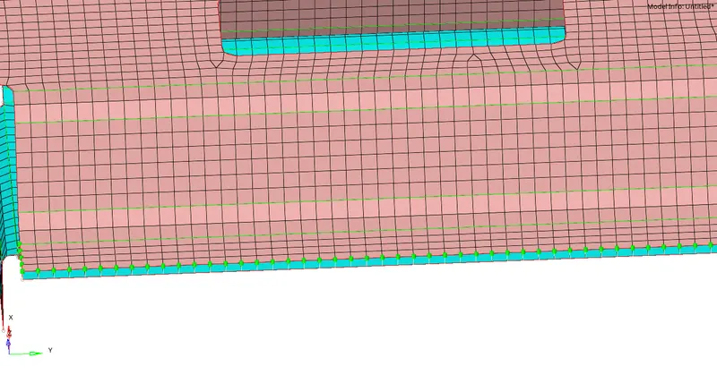
Now, for Left_Rail_1 & Left_Rail_2:- Spot-weld with Spring Elements
Use the above steps and just modify the type ( Spring) and click on create by selecting the respective nodes and components.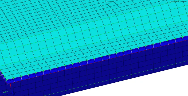
Rest all of the components were mostly connected using Spot welds >> type (Plot) for which the steps are already discussed above.
Thus, all the given components have been meshed and connected with the respective connectors.
INFERENCE:
In this challenge, usage of various types of connectors in the respective components has been learnt.