Week 12:Project-1-Meshing of Door Inner Panel Challenge
MESHING OF DOOR INNER PANEL
Automobile Door Inner Panel:
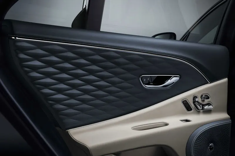
The Automobile door inner panel is a component which is used for strengthening the door assembly and it is one of the most important components in which all the accessories are mount like hinges, glass guide channel etc. They serve as an interface between the interior of the car and the inner workings of the door for which they should meet various design specifications along with safety, aesthetic appeal and functionality as this would be the part which would be continuously in touch and seen by the occupants in the vehicle.
OBJECTIVE :
To perform 2D meshing for the given side door panel with 4mm 2D quadrilateral elements according to the given quality criteria thereby performing topology clean up and extracting the midsurface. The meshed components are to be assigned with respective thickness value accordingly.
Here are the details of the given quality criteria to be followed:
Target Element Length = 4 Units
|
S.No |
Quality Criteria |
Value |
|
1 |
Aspect Ratio |
5 |
|
2 |
Skewness |
45 |
|
3 |
Warping |
15 |
|
4 |
Taper |
0.5 |
|
5 |
Min. Length |
2 Units |
|
6 |
Max. Length |
6 Units |
|
7 |
Min angle Quad |
45 |
|
8 |
Max angle Quad |
135 |
|
9 |
Min angle Tria |
20 |
|
10 |
Max angle Tria |
120 |
|
11 |
Tria % |
10 |
PROCEDURE:
WHY 2D MESHING?
In general, If the component has smaller thickness than its span length then it is mostly meshed with the 2D elements by clearing the topology from irregularities, extracting the midsurface, assign proper thickness and material properties and then mesh with 2D shell elements. By this method we can achieve the FE model with the original properties of the given geometric model.
Here, the given automobile door panel has variable thickness across its entire geometry and comparatively very large span length. Thus, 2D meshing can be carried out for the given model by following these steps:
GEOMETRY CLEANUP:
This is the first and foremost step involved in creating FE model. In this step the geometry needs to be cleared from all the geometric irregularities like duplicate surfaces, very small fillets (fails for minimum element size), missing surface, free edges, unwanted T-connections etc. In this model, the plastic component has several complex shapes like fixture pins, ribs etc which needs to be cleared from all the above-mentioned irregularities thereby it enhances the end result by providing better mesh flow and quality.
MIDSURFACE EXTRACTION:
This is the replica of the given geometry in 2D surface form which exactly matches with the parent geometry. This midsurface is where we work with meshing such that while assigning properties, materials the meshed FE model would be exactly the replica of the parent geometry. Here, the midsurface can be extracted by two methods: Manual midsurface and Auto midsurface.
Auto midsurface would be very much easier and straightforward when it comes to geometry of uniform thickness and easier shaped components. Most of the sheet metal components were uniform in thickness and they can be worked with auto midsurface extraction
Manual Midsurface would be precise and preferred mostly when it comes to components of complex structures and non-uniform thickness like in this case.
Most of the plastic components are of non-uniform thickness and manual midsurface is preferred for plastic components.
2D MESHING:
A 2D element is the two-dimensional phenomena of the solid which can either be three or four nodes (tria or quad elements). Meshing is general is creation of combination of all these tria or quad elements according to the shape of the parent geometry thereby these meshed models can be used for the analysis of our purpose. The choice of the meshing elements can be determined accordingly. Here, we mesh the midsurface with the 2D quad elements such that after assigning thickness it becomes a three-dimensional representation. This is done so as to drastically reduce the computational time and effort needed to mesh with 3D elements. Also, the 2D elements has their own set of advantages like:
1. Easier to manage and any modifications can be done easily
2. Reduces computational time and meshing time thereby leading to time efficient results.
STEPS TO BE FOLLOWED:
1. Import the respective side door panel geometry. Delete the solids as it is much easier for us to work in surfaces than solids.
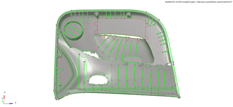
2. The geometry seems much complex and larger. In this case to make the work easier we can divide the whole geometry into smaller parts of our interest and so we can work on smaller parts and can then join them easily.
Go to Geometry --- Surface edit --- Trim with lines --- select the surface --- Drag cut line
By this method, we can segment the given model and can achieve results easier than working in the whole complex geometry.
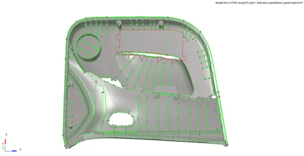
3. Now we can organize the segmented surface in different collectors for our convenience and can isolate the required surface. Tools --- Organize --- select the surface --- move
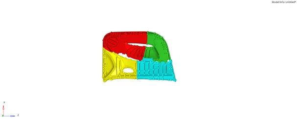
4. Now, we can work on separate smaller surface individually. Geometry clean up has to be done so as to remove all the irregularities in the surface like edge fillets, pinholes, surface errors etc., in order to get better mesh flow and element quality.
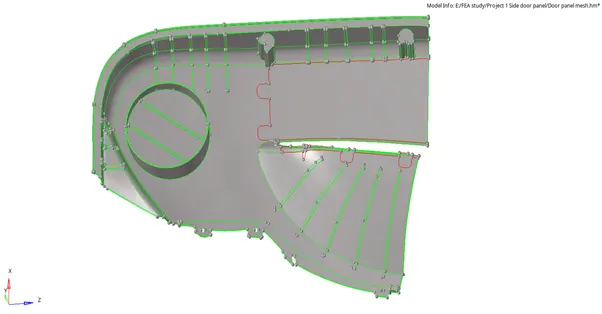
5. Now, to get the midsurface, we should measure each and every part in the component as they were of non-uniform thickness. Offsetting the surface to its midpoint would give us the midsurface. Go to Geometry – Surface edit – offset – Select the surface – Duplicate the surface to get new midsurface – provide vector direction properly – give the offset distance required – click offset to get the midsurface. Similarly, all the parts in all the components can be offset to get the middle surface accordingly.
6. Also, the same procedure is use to capture the midsurface for the ribs and other smaller parts in the component. But in this case the ribs are of varying in dimension throughout its span length. In this case we can use midline option to create the midsurface. Go to Geometry --- Lines --- Midline --- select the line list (both end line of ribs) --- click on create to get the midline of the rib.
Now, we can use that midline to trim the surface in reference with the midline. Go to Surface edit --- trim with lines --- select the surface --- select the line (midline of ribs) --- normal to surface and click on trim. We can get the surface trimmed with reference to the midline created.
Now, we can make use of both these lines (midline and surface edge) and use Ruled option in surface to create the midsurface of the rib.
Go to Surface --- Ruled --- Line list --- select both the lines and click create. We can get the rib which seems to be connected with the base surface.
If the rib is not connected with the base surface, go to surface edit --- extend surface --- extend over edges --- select the rib line --- select the target as base surface and click extend.
After extension, we can delete the excess part of the rib so as to get the perfect midsurface of the ribs.
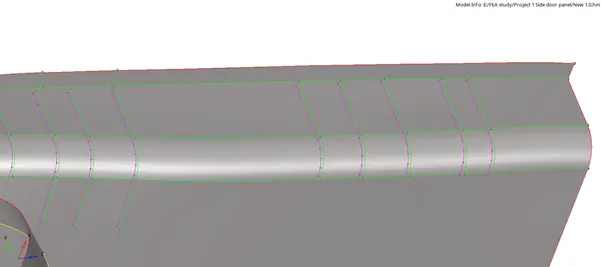
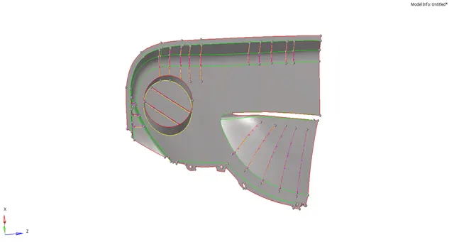
7. After creating all the midsurface of the segmented model, we should join them by using toggle edges option from the quick edit panel since we have made the whole model into smaller segments for easier progress.
Here is the midsurface of the complete model with all the special features captured and equivalenced.
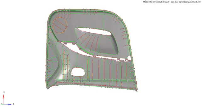
Certain features will be tough to handle due to the spline surface which is quite hard for the software to handle it. In such cases we can extract the lines from those surfaces, recreate those spline surface and then we can work on it to get it easier.
8. Now, we can start meshing all the components by using 2D quad elements. By setting all the quality criteria in the criteria section and selecting target element size as 4mm and mixed type of elements all the components which are segmented can be meshed separately in different collectors such that it will be used to equivalence all the elements easily.
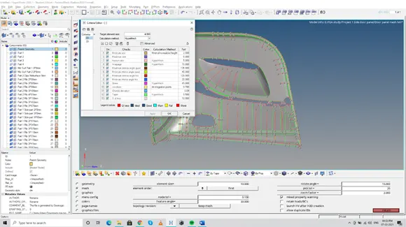
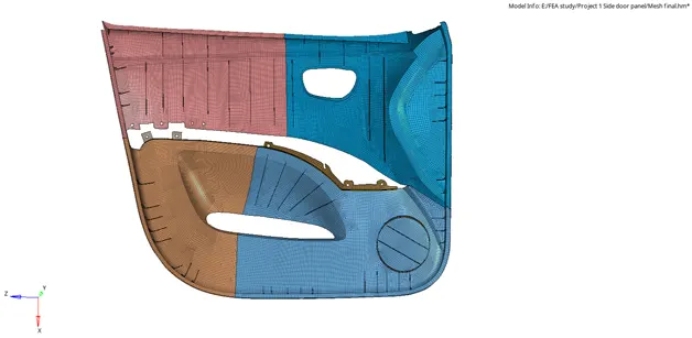
9. After meshing all the components and clearing all the quality criteria, we should create properties with all the range of thickness present in the geometry such that they should be assigned properly for all the surface accordingly.
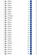
10. Now, all the surface parts are to be assigned with the respective properties by right clicking on the collector in which the parts are and assigning the respective property.
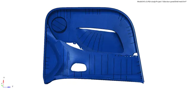
RESULT :
Thus, the FE model of the side door panel with the required parameters and quality criteria has been created successfully.
INFERENCE :
Apart from geometry clean up and 2D meshing these are certain things which we can learn from this exercise :
1. Usage of manual midsurface by offset method.
2. Splitting complex structures into smaller parts to work easily.
3. Recreation of complex spline surface by using lines and creation of ribs with various methods like midline creation etc
4. Joining of special components like ribs to base surface by using extend surface option.
5. Creation of properties and assigning thickness to the 2D elements to get the precise FE model.