Week 8-3D Tetra Meshing Challenge
AIM :
To perform 3D tetra meshing for the given components which satifies the given element quality parameters
PROCEDURE :
In this part, we need to perform 3D meshing with tetra elements of size 5mm and min & max element size as 2mm & 7mm accordingly with tet collapse not lesser than 0.15
For the Housing model,
1. This Housing has 2 components and so it should be meshed seperately. Since it is easy to work with surfaces, delete the solids present in the given component as usual.
2. Now, check for the irregularities present in the given component and then perform the geometry cleanup thereby optimizing the surface fillets which are of smaller than the minimum element length which is 2mm.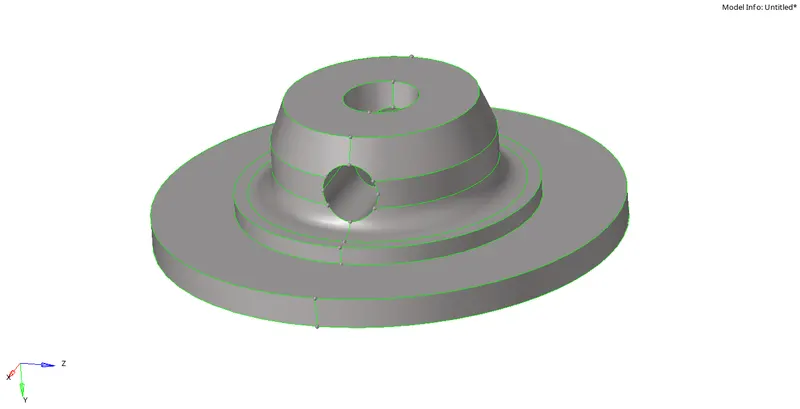
3. Now, after cleaning up the geometry, first we should perform 2D automesh with tria elements only and target element size as 5mm and then we can use those 2D elements to perfrom tetrameshing to get the desired 3D elements of 5mm target size.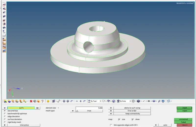
4. After meshing, check for the minimum and maximum element size of the elements which are between 2mm and 7mm respectively. Remesh the elements if the 2D elements created were failing for min & max element size.
5. After successful creation of 2D trias then move to the 3D tab in the main menu and select tetrameshing. Now, In the tetramesh tab, to select the entities, click on the drop down arrow and select elements.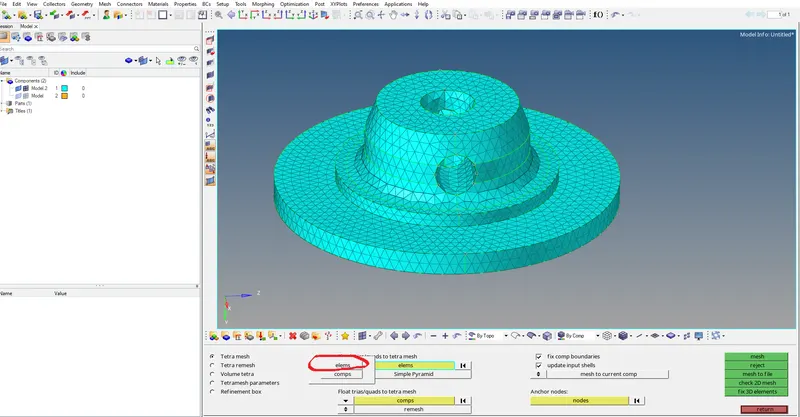
6. Now, select all the 2D elements and then proceed with meshing. Thus, the 3D tetra mesh has been successfully created.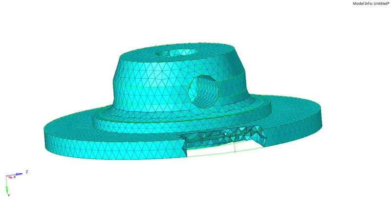
7. Now, for checking the element quality, press F10 from the keyboard and go to 3D tab. Now, click on the tet collapse option to check whether all the tetra elements has passed the tet collapse value 0.15
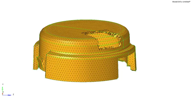
If there are failed elements, save the failed elements, go to mask option by pressing F5 in the keyboard and rightclick on elements and select retrieve to select the failed elements. Now, mask the failed elements and reverse them to view all the elements which were failing for the tet collapse value.
8. In order to clear those failed elements, we need to remesh all the elements again so as to pass the tet collapse parameter. Again go to 3D tab>>Tetramesh>>Tetramesh parameters>> tet collapse >> enter the desired tet collapse value 0.150
9. Now, go to tetra remesh option and select the entities as elements and select all the elements to remesh. Now, the remesh has been done.
10. Thus, the elements were remeshed and has passed the tet collapse value not lesser than 0.15. By following the similar steps, the other component shall also be meshed with 3D tetra elements by first meshing it with 2D trias and using those as reference, create 3D tetra elements.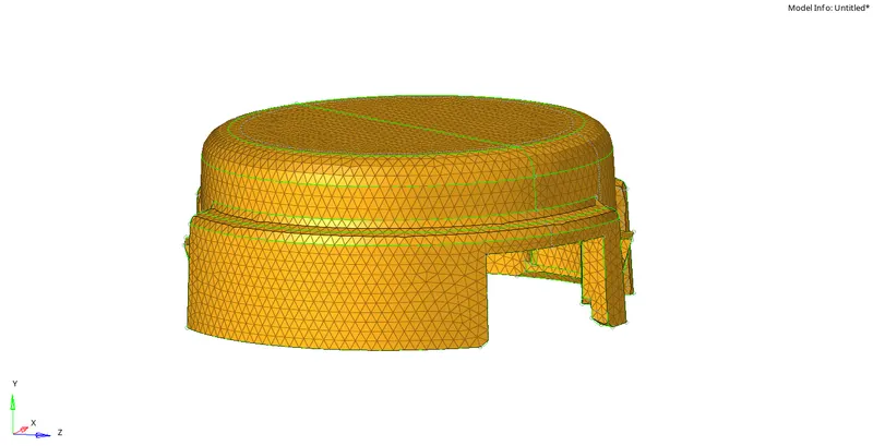
FOR THE OTHER MODELS:
1. Import the next model which is the crank housing. In this component, we have to mesh the component with 6mm tetra elements. The tet collapse remains the same as 0.15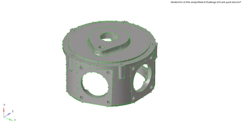
2. For this requirement there is an easy method to directly mesh the component with tetra elements of 6mm size. The option which is used for this kind of meshing is QuickTetra.
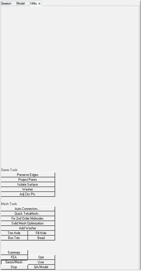
3. To select the quick tetra, go to View in the top tool bar, go to Browsers, select Hypermesh and select Utility. Then the Utility tab would open in the left side of the user window.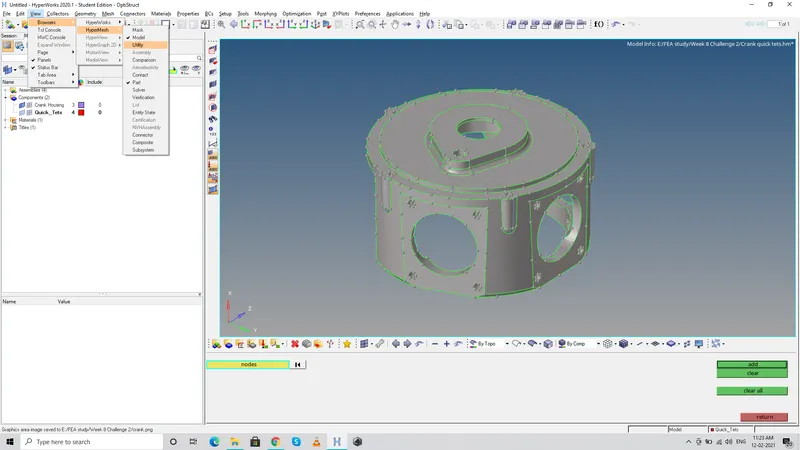
4. Now, in the utility tab, select geom/mesh option and select Quick tetramesh. The Quick tetramesh window would open with several options to edit the mesh criteria like element size, type of element etc.,
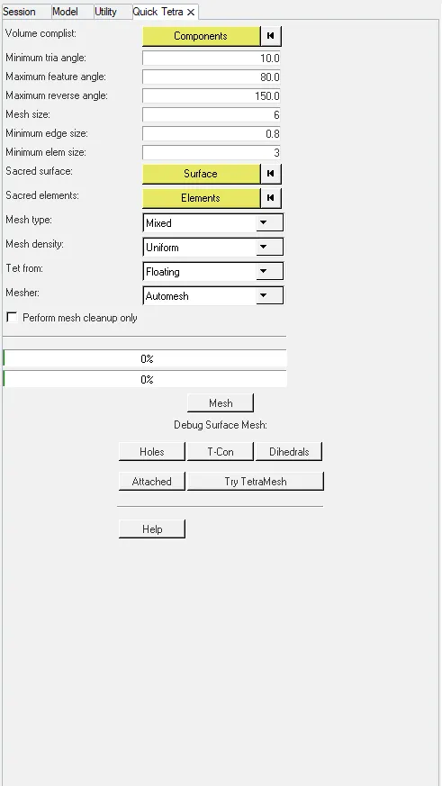
5. Enter the Mesh size as 6mm and type of element to trias only from the drop down list . Now, click on the Mesh button. As soon as the mesh is clicked, component would be cleaned up and meshing would be done automatically with 3D tetra elements of size 6mm.
After meshing, a new collector called as quick tets would be created which comprises of the component which has been meshed successfully with the 3D tetra elements.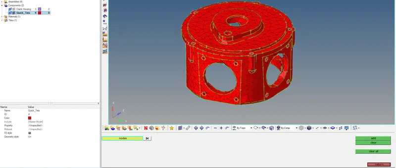
6. Thus, the component has been successfully meshed with 6mm tetra elements and similarly, If there are any tet collapse elements, we can remesh them by the same method which was already discussed.
NEXT MODEL:
1. Import the next model which has more than 1 component and thus each component can be meshed seperately and held within seperate collectors.
2. Now, firstly start with the first component and check for the irregularities in the component like duplicate surface, incomplete surface, fillets which would fail for the min.element size etc and the remove those features to completely clean up the geometry.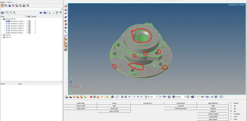
3. All the fillets can be removed by using the defeature command present in the geometry tab and the surf fillets which are of size lesser than the min.elem size can be removed. Also in this component there are number of teeth arrangements which cannot be captured perfectly by the elements, so we have to remove those teeths as well.
4. To remove the teeth, firstly we can seperate all the teeth into seperate surfaces by trimming the surface lines by using node to node trim option from the quick edit tab.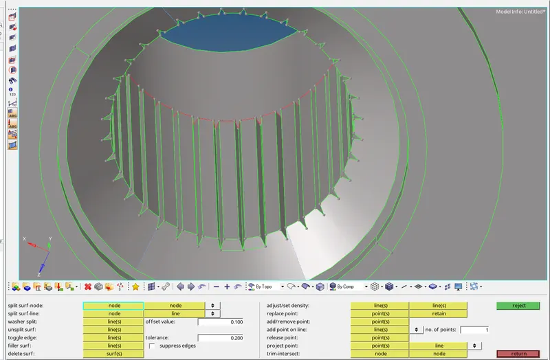
5. Similarly in the other side, the individual teeths can be trimmed into seperate surfaces and then all the teeths should be deleted. In order to avoid other mistakes, we can mask the teeths manually and then delete those teeth alone so as to avoid any mistakes by deleting the other surfaces.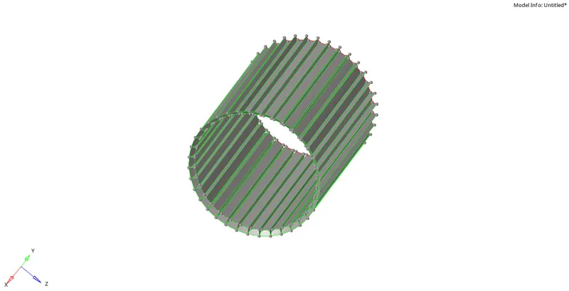
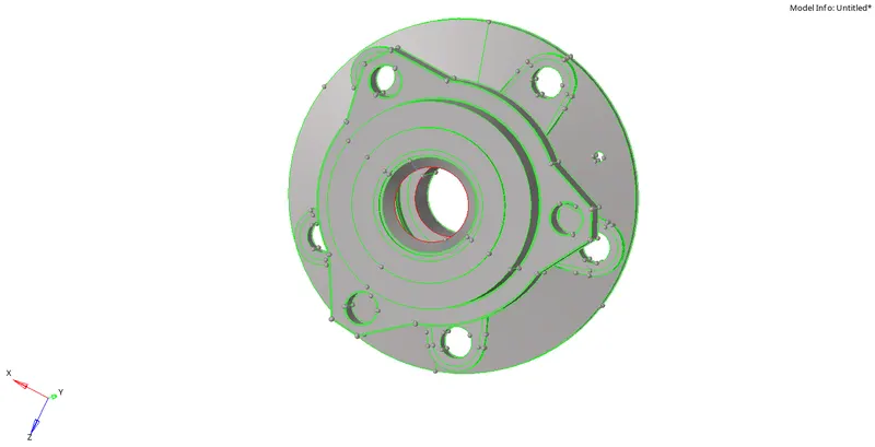
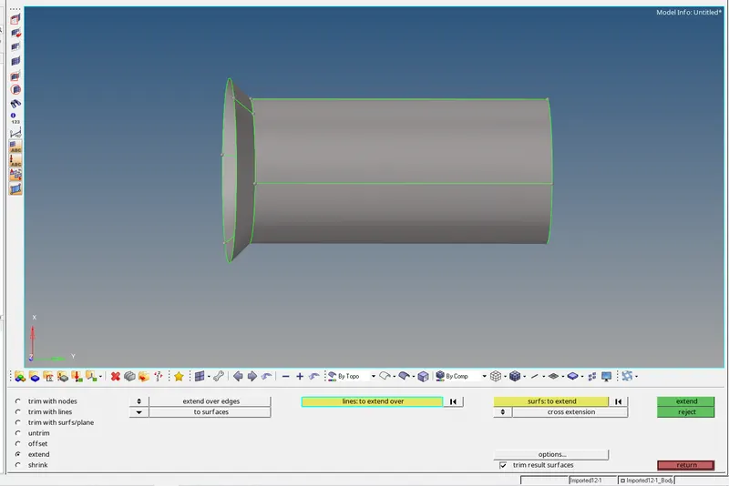
6. After deleting the teeths, the surface has to be filled with planes and so, we can use extend surface over edges command in the surface edit option present in the geometry tab. Similarly we can mask the surfaces in which we need to work to avoid the confusion and then extend one surface to other to fill the surface gaps, In case of any misalignment, delete the intermediate surface close to the edge where it needs to be pasted and repeat the same procedure of extending the surface. Thus, the teeth has been removed and the surface gap has been filled with plane surfaces which makes the geometry ready to be meshed.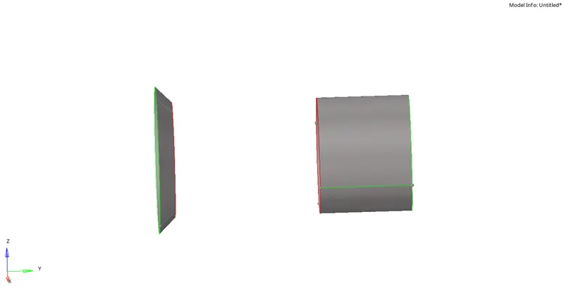
7. After successful cleanup of the component, the steps which are followed in the previous model can be used here to mesh, Firstly create 2D trias of element size 6mm and then those elements as reference we can create 3D tetramesh. Here to avoid the tet collapse failure, we can set the mesh parameter by providing the tet collapse min as 0.15 in order to avoid element failure.
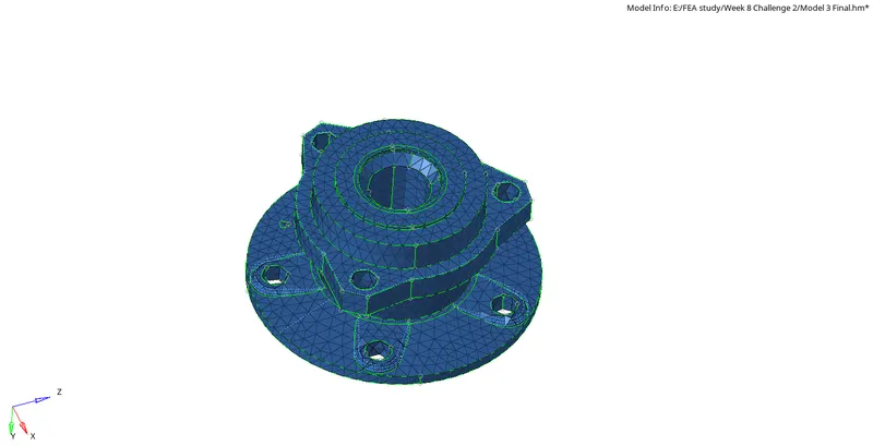
8. Thus the component has been meshed with 3D tetra elements of size 6mm and similarly we can mesh all the other components seperately by first cleaning the geometry followed by 2D tria mesh and then 3D tetra meshing with mesh criteria of tet collapse not lesser than 0.15
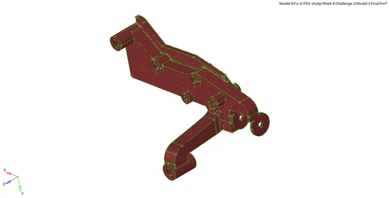
Here are the images of the other components meshed with 3D tetra elements: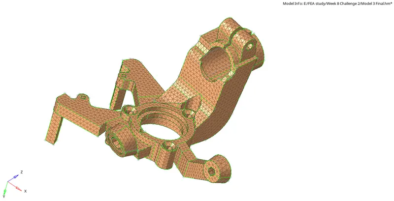
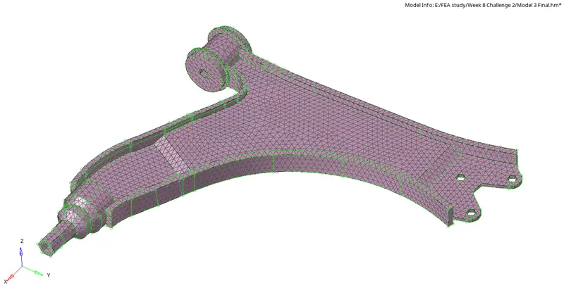
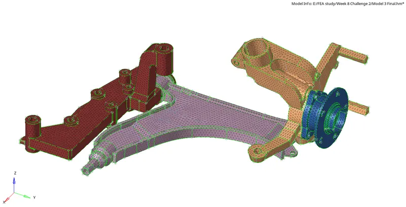
RESULT:
Thus the given components has been meshed successfully with the 3D tetra elements which passes the given quality parameters.
INFERENCE:
From this exercise, I've learnt how to perform 3D tetra meshing using various options like direct 3D tetra mesh, usage of Quick tetramesh and using 2D tria as reference and creating 3D elements out of it, Also optimization of those elements which were failing for the tet collapse by setting mesh criteria and remeshing.