Week 6- Challenge
Aim :
To extract midsurface of the given component for each parts seperately and then perform 2D meshing with the given parameters.
Procedure :
1. Firstly, Import the given .hm file in the altair hyperworks window and then view the geometry.
2. After analysing the geometry, start from the smallest component of the geometry. In this case, start the meshing from the latch component of the given geometry.
3. Now, Other than the Latch reinforcement, hide the other components and then delete all the solids of the given component as we don't perform meshing in the Solids.
4. After deleting the solids, check for the geometric irregularities and then proceed with cleanup of the component. After cleaning up the component the midsurface of the geometry should be extracted as usual by using auto midsurface option.
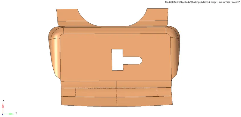
5. Now, the surface needs to meshed with 2D meshing with the target element as 5mm. Now, go to 2D in main menu bar >> automesh >> select surface >> fix element size >> select elements as "mixed" and then proceed with meshing.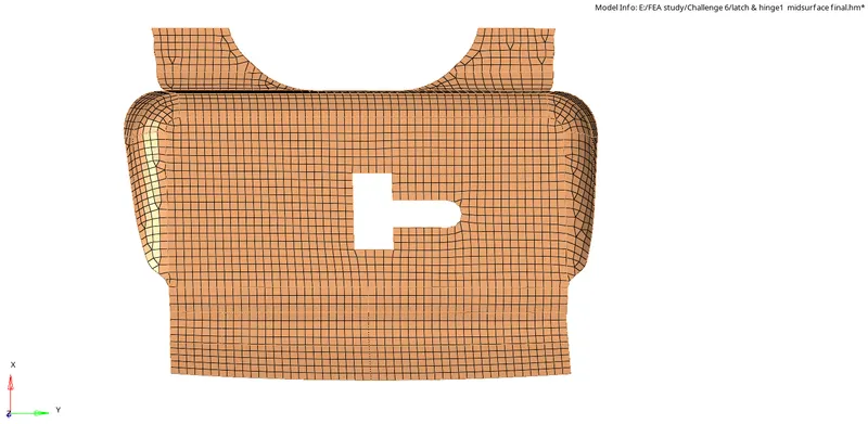
6. After the mesh has been generated, check for all the given parameters and try to avoid all the rotational quad elements and oppositely faced triangular elements by remeshing those elements.
Remeshing elements can be done in the same manner as we use to perform surface meshing. In the same tab, change the entity to elements instead of surface and select the required elements and then proceed with remesh to correct those irregularities.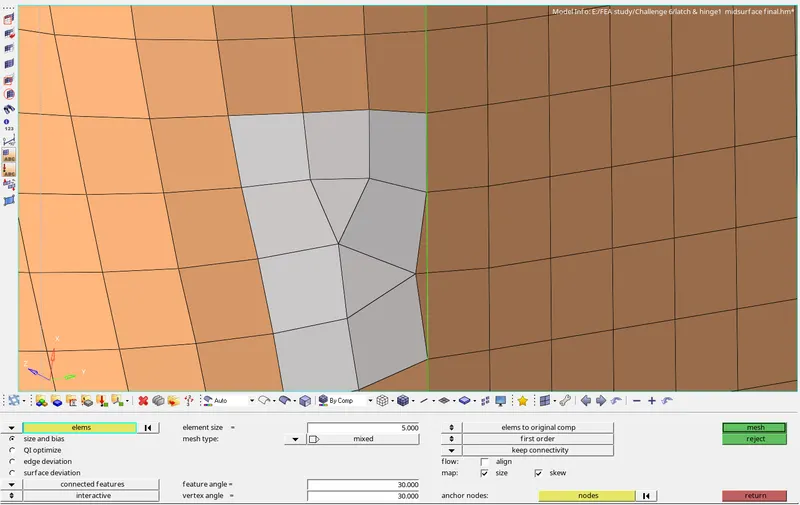
7. Now, check for similar irregular elements all around the geometry and eliminate those elements as much as possible to get a quality meshing.
Then, there are other options to be considered to correct or edit the element qualities, they are seen in 2D>>Quality Index>> Clean up tools
Some commonly used cleanup tools were :
Place node : Used to pick a node in the element and drag the element to change the element geometry, It is generally used when the element fails for max.element length (8mm) and min.element length (2mm)
Element Optimize : Used to optimize all the irregular parameters of the element in a single click. Mostly used to correct the irregular elements which fails for warpage,skew,Jacobian.,etc
Smooth : This option is used to smooth the element columns if they appear to be very much distorted after several irregular elements have been removed.
Drag Tria Element : This option as the name suggests is used to drag the triangular elements in between the meshed surface as we don't need tria elements for this case. Simply by clicking on the respective tria element and dragging it out, the tria element can be removed.
Split Quad Element : This option is used to split the quad element which are of much larger size into triangular elements. After doing this, it is recommended to remesh those particular elements to get the irregularities cleared.
Combine Tria Element : It is used to combine smaller tria elements which are in present in opposite faces together so as to create a single quad element and optimizing that quad element would give a better result.
Edit element : This is seen in 2D menubar, As the name suggest it is used to edit the element for the following options: Create, Combine & Split.
Element Cleanup : This is used to clear the element which is failing for all the parameters. It is generally indicated as red colored element. The respective element has to be selected and clicking on cleanup would give the proper element.
These are the tools which were commonly used to cleanup the elements to meet the required quality parameters.
To check the elements for the required quality parameters, go to Tools>>check elem>> (shortcut F10) provide the values of the given quality parameters and click on the parameter. It will indicate the number of elements which were failed for the respective parameter and it will also be indicated in the graphics area as highlighted element.
Thus, all the quality parameters can be checked for all the meshed geometry and the corresponding counter actions were done to correct the irregular elements which fails for the quality parameters.
Here is the meshed component :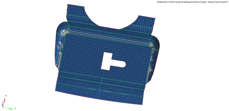
These same procedures were to be repeated for all the parts of the geometry and required corrective actions were took by using those tools which were mentioned before to edit the element.
Some geometry might differ in their structure such that meshing those component would be hard than this component, In such parts, the midsurface needs to be edited and the surface has to be split up accordingly in order to get proper meshing.
Here are the pictures of the other parts of the component which were cleared and meshed properly according to the given quality parameters.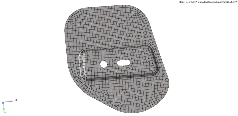
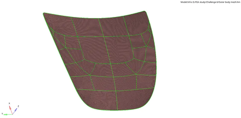
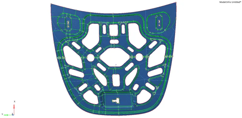
Result:
Thus the given component has been meshed seperately by segregating all the components and extracting the midsurface and meshing with 2D elements accordingly.
Inference:
In this module, I've learnt about usage of all the tools and options available in 2D tab and usage of techniques like seperation of complex structures into linear to enhance the mesh flow and connectivity.
Also I've learnt to check for the symmetry of the geometry so as to make use of reflect command in tool to mesh the symmetric components easily within lesser time period.