Week 9-Creation of 1D Connectors Challenge
Objective:- To mesh the given model and create 1D,2D connector to each parts by given data as follows:
1. Right_Rail_2 & Front_truss_1:- Seam-Quad(angled+capped+L)
1.1.Front_truss_2 & Right_rail_2:- Seam-Quad(angled+capped+L)
2. Left_Rail_2 & Front_truss_1:- Quad elements
2.1.Front_truss_2 & Left_rail_2 :- Quad elements
3. Front_truss_2, Front_truss_1 & Right_Rail_1:- Spot weld with 2 Layers and 5 mm Diameter
4. Front_truss_2, Front_truss_1 & Left_Rail_1:- Hexa (Adhesive)
5. Rear_truss_2 & Right_Rail_2:- Bolt Connector
6. Rear_truss_2 & Left_Rail_2:- Bolt Connector
7. Right_Rail_1 & Right_Rail_2:- Spot-weld with Rigid Elements
8. Left_Rail_1 & Left_Rail_2:- Spot-weld with Spring Elements
9.Refine_plate & Front_truss_1, Front_truss_2:- Spot-weld with Bar2 Element
10.Right_Rail_1 & Rear_truss_2 :- Spot-weld with Rigid Elements
11.Left_Rail_1 & Rear _truss_2 :- Spot-weld with Rigid Elements
12.Rear_truss_1 & Rear_truss_2 :- Spot-weld with Rigid Elements
Procedure:-
1.Firstly, Import the model.
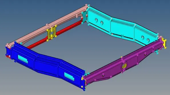
2.Then, mesh the all the part with given data.
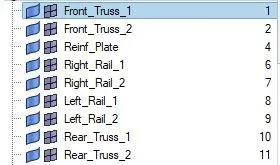
3.All the parts are mesh and also check the quality criteria.

Final Mesh:
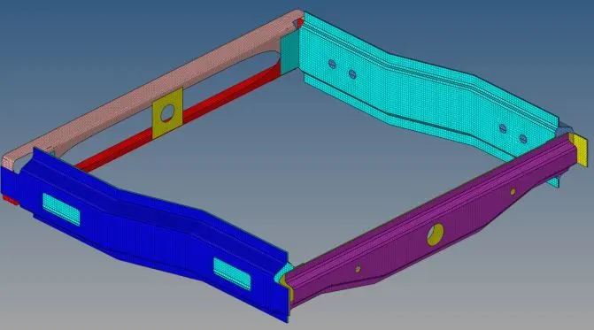
4.Now, assign the property and material.
1D connections
1. Right_Rail_2 & Front_truss_1:- Seam-Quad(angled+capped+L)
To create a seam weld,
Command:- [1D/2D >>connectors>>seam>>select nodelist>>spacing-5mm>>tolerance-10mm>>type- Seam-Quad(angled+capped+L)>>weld angle-45/60>>create]

- Select nodelist by path on one component.
- Select spacing based on the target element size which is 5mm. Or
- Select density based on the total number of nodes.
- Select the two components.
- Tolerance should be double than the distance between two components.
- Type is Seam-Quad(angled+capped+L).
- Weld angle is may be 60 or 45 based on the components.
- Lastly, check the imprint and create.
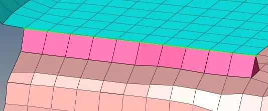
1.1.Front_truss_2 & Right_rail_2:- Seam-Quad(angled+capped+L)
All the procedure are same.
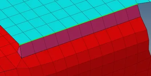
2. Left_Rail_2 & Front_truss_1:- Quad elements
Command:- [1D/2D >>connectors>>seam>>select nodelist>>spacing-5mm>>tolerance-10mm>>type- Seam-Quad>>create]

- Select nodelist by path on one component.
- Select spacing based on the target element size which is 5mm.
- Select the two components.
- Tolerance should be double than the distance between two components.
- Type is Seam-Quad
- Lastly, check the imprint and create.
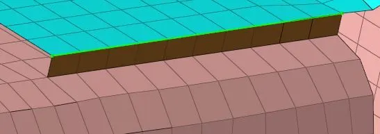
2.1.Front_truss_2 & Left_rail_2 :- Quad elements
All the procedure are same as above.
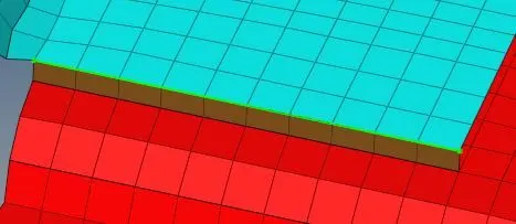
3. Front_truss_2, Front_truss_1 & Right_Rail_1:- Spot weld with 2 Layers and 5 mm Diameter.
Command:- [1D/2D >>connectors>>spot>>select node>>tolerance-10mm>>type- Weld>>diameter-5mm>>num layer-total 2>>create]

- Select the nodes by path on one component.
- Select the two component.
- Select number layer Total 2 as per given.
- Tolerance is also 10mm and diameter is 5mm given.
- Select type is weld.
- Lastly, press create tab.
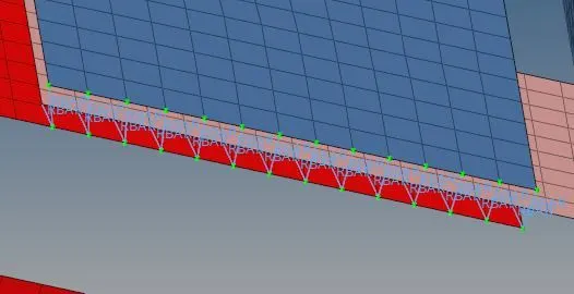
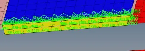
4. Front_truss_2, Front_truss_1 & Left_Rail_1:- Hexa (Adhesive)
Command:- [1D/2D >>connectors>>seam>>select nodelist>>spacing-5mm>>tolerance-10mm>>type- Hexa(Adhesive)>>create]

- Select nodelist by path on one component.
- Select spacing based on the target element size which is 5mm.
- First, select the two components.
- After that select another two component.
- Tolerance should be double than the distance between two components.
- Type is Hexa(adhesive).
- Strips and coats is 1 as data not given so select 1 for both.
- Lastly, press create tab.
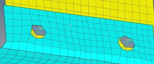
5. Rear_truss_2 & Right_Rail_2:- Bolt Connector
Command:- [1D/2D >>connectors>>bolt>>select node>>tolerance-10mm>>type-Bolt(general) >>create]

- Select by node and put the node on that point where the bolt connection create.
- Select both component.
- Tolerance is 10mm.
- Type is bolt(general)
- Most important select create hole, if none.
- Lastly, create the bolt connection.
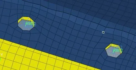
6. Rear_truss_2 & Left_Rail_2:- Bolt Connector
All the procedure are same as above.
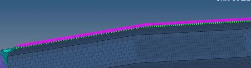
7. Right_Rail_1 & Right_Rail_2:- Spot-weld with Rigid Elements
Command:- [1D/2D >>connectors>>spot>>select node>>tolerance-10mm>>type- Rigid >>create]

- Select the nodes by path on one component.
- Select the two component.
- Select number layer Total 2 as per given.
- Tolerance is also 10mm.
- Select type is rigid.
- Lastly, press create tab.
- Do same to both side of component.
8. Left_Rail_1 & Left_Rail_2:- Spot-weld with Spring Elements
Command:- [1D/2D >>connectors>>spot>>select node>>tolerance-10mm>>type- Spring >>create]

- Select the nodes by path on one component.
- Select the two component.
- Select number layer Total 2 as per given.
- Tolerance is also 10mm.
- Select type is Spring.
- Lastly, press create tab.
- Do same to both side of component.
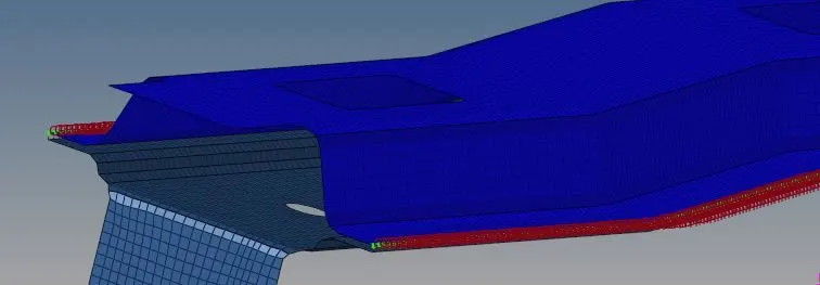
Following components are left so join them with suitable connectors.
9.Refine_plate & Front_truss_1, Front_truss_2:- Spot-weld with Bar2 Element
Command:- [1D/2D >>connectors>>spot>>select node>>tolerance-10mm>>type- Bar2 >>create]

- Select the nodes by path on one component.
- Select the two component.
- Select number layer Total 2 as per given.
- Tolerance is also 10mm.
- Select type is Bar2.
- Lastly, press create tab.
- Do same to both side of component.
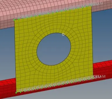
10.Right_Rail_1 & Rear_truss_2 :- Spot-weld with Rigid Elements
Command:- [1D/2D >>connectors>>spot>>select node>>tolerance-10mm>>type- Rigid >>create]

- Select the nodes by path on one component.
- Select the two component.
- Select number layer Total 2 as per given.
- Tolerance is also 10mm.
- Select type is rigid.
- Lastly, press create tab.
- Do same to both side of component.
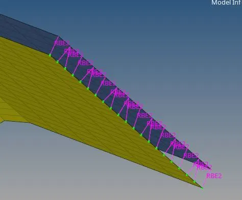
11.Left_Rail_1 & Rear _truss_2 :- Spot-weld with Rigid Elements
All the procedure are same as above.
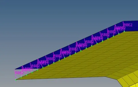
12.Rear_truss_1 & Rear_truss_2 :- Spot-weld with Rigid Elements
Here also all the procedure are same as above.
- Select the nodes by path on one component.
- Select the two component.
- Select number layer Total 2 as per given.
- Tolerance is also 10mm.
- Select type is rigid.
- Lastly, press create tab.
- Do same to both side of component.
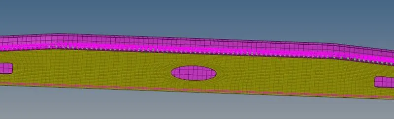
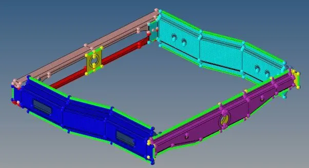
Final Model:-
Conclusion:-
1.In this challenge , we mesh the component and learn about various types of connectors.
2.All the component are successfully realized.