Week 9-Creation of 1D Connectors Challenge
AIM To mesh the frame assembly and make connection representation at specified parts.
CONNECTIONS :
1. Right_Rail_2 & Front_truss_1:- Seam-Quad(angled+capped+L)
2. Left_Rail_2 & Front_truss_1:- Quad elements
3. Front_truss_2, Front_truss_1 & Right_Rail_1:- Spot weld with 2 Layers and 5 mm Diameter
4. Front_truss_2, Front_truss_1 & Left_Rail_1:- Hexa (Adhesive)
5. Rear_truss_2 & Right_Rail_2:- Bolt Connector
6. Rear_truss_2 & Left_Rail_2:- Bolt Connector
7. Right_Rail_1 & Right_Rail_2:- Spot-weld with Rigid Elements
8. Left_Rail_1 & Left_Rail_2:- Spot-weld with Spring Elements
9. Rest all the component left Join them with suitable connectors
PROCEDURE :
A. Meshing :
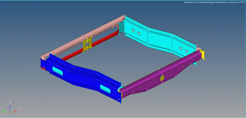
1. Import the frame_assembly_welding.hm to hyper mesh under optistruct profile.
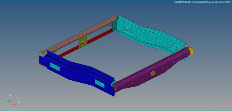
2. 2D > Automesh the component with 5mm as target element size as the mid surface is available.
B. Connections :
1. SEAM WELD CONNECTION
- Hide all components except right rail 2 and front truss 1.
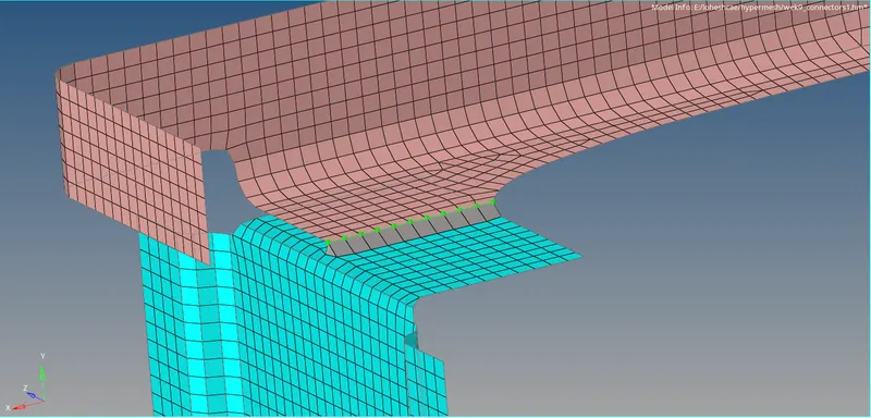
- 1D > connectors > seam type as seam-quad(angled+cappled+L)
- Select the node list on front truss and components to connect, with remesh option.
- Increase tolerance value to 10 and Click create and remesh the area for proper mesh flow.
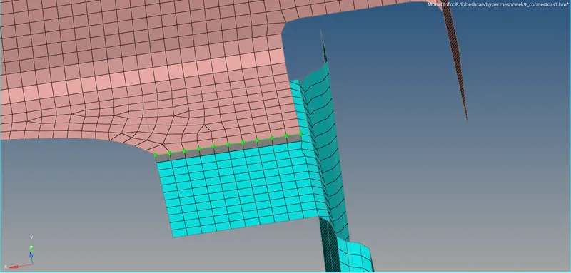
2. QUAD ELEMENTS
- Hide all components except left rail 2 and front truss 1.
- 1D > Connectors > Seam and type as quads.
- Create a property for quad elements and assign.
- Select the node list on the front truss and components to connect, with remesh option.
- Increase tolerance value to 10 and Click create and remesh the area for proper mesh flow.
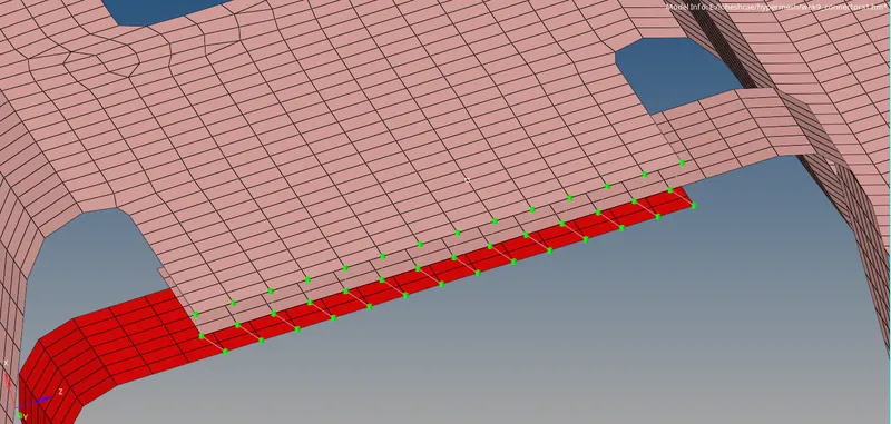
3. SPOT WELD
- Hide all components except Front truss 2, Front truss 1, and right rail 1.
- 1D > connectors > spot type as weld , diameter as 5mm.
- Select the nodes to spot weld and components to connect with 2 layers.
- Create a property for spot weld and assign. Click create with tolerance 20.
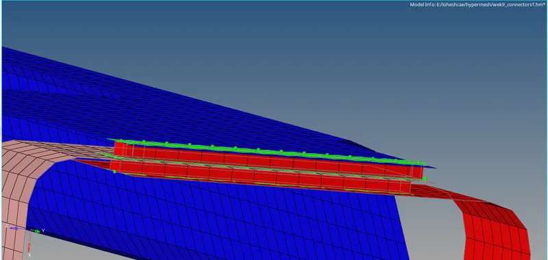
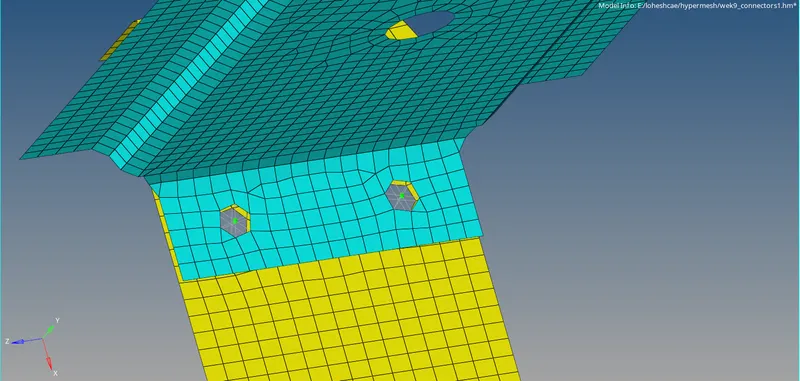
4. HEXA ADHESIVE CONNECTOR
- Hide all components except Front_truss_2, Front_truss_1 & Left_Rail_1 .
- 1D > connectors > seam type as Hexa (adhesive).
- Increase tolerance to 50, select nodes in one component, and select components to connect. Create.
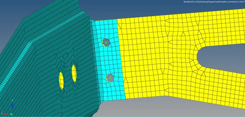
5. BOLT CONNECTOR
- Hide the components except Rear_truss_2 & Right_Rail_2.
- 1D > Bolt type as Bolt (general).
- Select the nodes and components to connect.
- Increase tolerance to 10 and select create bolt if necessary.
6. Rear_truss_2 & Left_Rail_2:- Bolt Connector
same process followed here
7. SPOT WELD WITH RIGIDS
- Hide all components except Right_Rail_1 & Right_Rail_2.
- 1D > Connectors > spot type as rigids select nodes to connect. Assign property.
- Select components to connect after increasing tolerance to 10 and create.
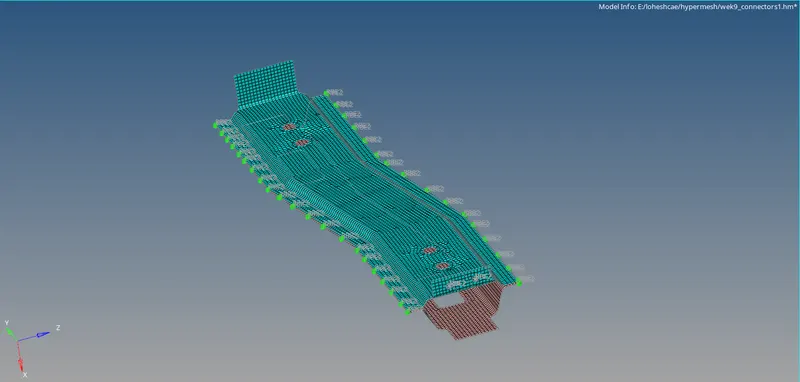
8. SPOT WELD WITH SPRINGS
- Hide all components except Left_Rail_1 & Left_Rail_2.
- 1D > Connectors > spot type as springs select nodes to connect. Assign property
- Select components to connect after increasing tolerance to 50 and create.
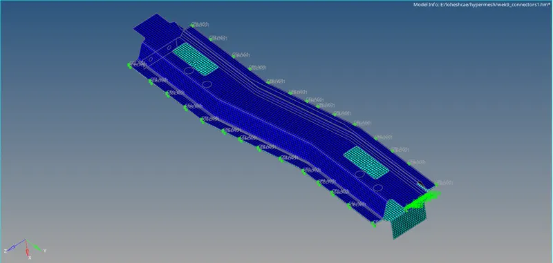
9. Remaining components are connected using seam weld, spot weld by following the above steps.
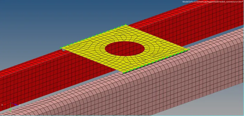
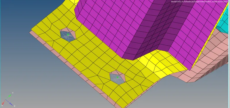
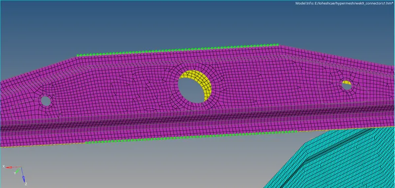
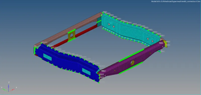
Final image after connections