Week 9-Creation of 1D Connectors Challenge
Objective : Creation of different types of 1D connector to join two or more components.
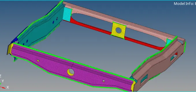
- Given model is already having the mid surface of the component. It is directly meshed using 'automesh option with element size of 5mm with mixed element type
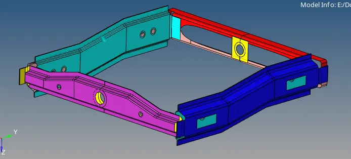
- All the connectors were applied one by one as follows:
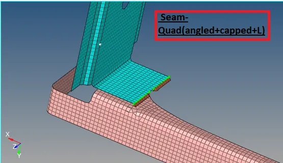
1) Seam-Quad(angled+capped+L)
- We have to create Seam-Quad(angled+capped+L) connector on Right Rail2 & Front truss1.
- For that first of all we need to mesh Right Rail2 and Front Truss1 with 'mixed mesh' type using 'automesh' tool in '2D' panel.
- Then go to 'connector' tool in '1D' panel. use appropriate connector for this case we select 'seam' type connector then select parallel surface of components to create connector.
-
Select type-seam-quad(angled+capped+L) spacing-5, tolerance -10, weld angle - 45, cap angle - 60, runoff angle - 10, property-Frame assembly, components - Right Rail_2 & Front_truss_1 and we need to select nodes where connector is to be create.



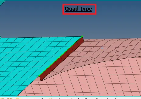
2) Quad elements
- We have to create Quad elements type of connector on Left Rail2 & Front truss1.
- First mesh the components Left Rail2 & Front truss1 with 'mixed mesh' type using 'automesh' tool in '2D' panel.
- Then we hve to go 'connector' tool in '1D' panel. use appropriate connector for this case we select 'seam' type connector then select parallel surface of components to create connector.
- Select type-quad, spacing-5, tolerance -10, weld angle - 45, cap angle - 60, runoff angle - 10, property-Frame assembly, components - Left Rail2 & Front truss1 and we need to select nodes where connector is to be create.

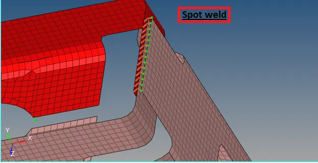
3) Spot weld
- We have to create Spot weld connector on Front truss2, Front truss1 & Right Rail1.
- For that first of we need to mesh Front truss2, Front truss1 & Right Rail1 with 'mixed mesh' type using 'automesh' tool in '2D' panel.
- Then go to 'connector' tool in '1D' panel. use appropriate connector for this case we select 'Spot' type connector then select parallel surface of components to create connector.
- We have to select type - plot, spacing-5, tolerance -10, diameter - 5, num layers - total 3, property-Frame assembly, components - Front truss 2, Front truss1 & Right Rail1, select nodes where connector is to be create.

4) Hexa (Adhesive)
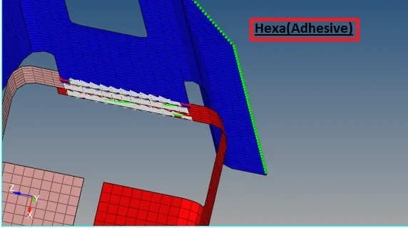
- We have to create Hexa (Adhesive) connector on Front truss2, Front truss1 & Left Rail1
- For that first of all we need to mesh Front truss2, Front truss1 & Left Rail1 with 'mixed mesh' type using 'automesh' tool in '2D' panel.
- Then go to 'connector' tool in '1D' panel. use appropriate connector for this case we select 'seam', 'Hexa (Adhesive)' type connector then select parallel surface of components to create connector.
- Select type-seam-Hexa (Adhesive) spacing-5, tolerance -10, weld angle - 45, cap angle - 60, runoff angle - 10, property-Frame assembly, components - Front truss2, Front truss1 & Left Rail1 and we need to select nodes where connector is to be create. This connector is created 'RBE 3' link.

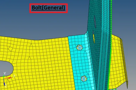
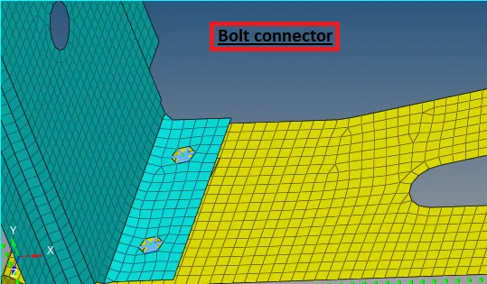
5) Bolt Connector
- We have to create Bolt connector on Rear truss2 & Right Rail2.
- For that first of we need to mesh Rear truss2 & Right Rail2 with 'mixed mesh' type using 'automesh' tool in '2D' panel.
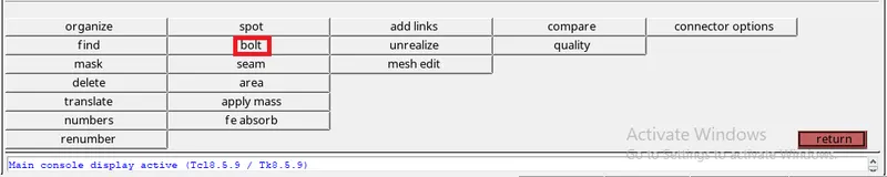
- Then go to 'connector' tool in '1D' panel. use appropriate connector for this case we select 'Bolt' type connector then select parallel surface of components to create connector.
- We have to select type - bolt(genral), tolerance -10, num layers - 2, components - Rear truss2 & Right Rail2, select nodes where connector is to be create.
6) Bolt connector
- Follows same process as previously followed to create bolt connector on Rear truss2 & Left Rail2.
7) Spot-weld with Rigid Elements
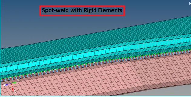
- We have to create Spot weld with rigid elements connector on Right Rail1 & Right Rail2
- For that first of we need to mesh Right Rail1 & Right Rail2 with 'mixed mesh' type using 'automesh' tool in '2D' panel.
- Then go to 'connector' tool in '1D' panel. use appropriate connector for this case we select 'Spot' type connector then select parallel surface of components to create connector.
- We have to select type - Rigid, spacing-5, tolerance -10, diameter - 5, num layers - 2, property-Frame assembly, components -Right Rail1 & Right Rail2 , select nodes where connector is to be create. This connector is created 'RBE 2' link.

8) Spot-weld with Spring Elements
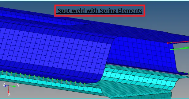
- We have to create Spot weld with Spring elements connector on Left Rail1 & Left Rail2
- For that first of we need to mesh Left Rail1 & Left Rail2 with 'mixed mesh' type using 'automesh' tool in '2D' panel.
- Then go to 'connector' tool in '1D' panel. use appropriate connector for this case we select 'Spot' type connector then select parallel surface of components to create connector.
- We have to select type - Spring, spacing-5, tolerance -10, diameter - 5, num layers - 2, property-Frame assembly, components -Left Rail1 & Left Rail2 , select nodes where connector is to be create. This connector is created CLEAS elastic elements.

Final Model With Different Connectors