Week 9 Challenge
1. Data Given:-
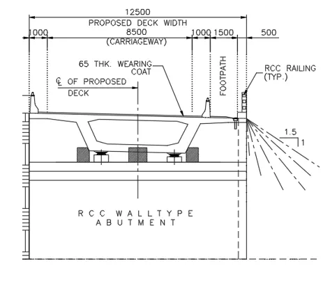
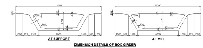
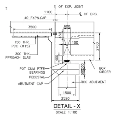
Length of the linear waterway = 90 m
Design discharge = 700 m3/s
Silt factor = 1
HFL = 3 m from GL
Velocity of water = 1.2 m/sec.
Top road level = 100 m
Ground Level = 93.5 m
HFL= 96.5 m
Diameter of Pile = 1.2 m
Vertical capacity = 250 tonnes
Horizontal capacity = 35 tonnes
Well Diameter = 8 m
Capacity = 70 tonnes/m2.
Well Diameter = 6 m
Capacity = 50 tonnes.
Well Diameter = 7 m
Capacity = 60 tonnes/m2.
Scouring in River:-
The removal of sediment or engineered materials from the bed or banks of a watercourse is known as ‘river scour’ and can occur when the forces imposed by the flow on a sediment particle exceed the stabilising forces (Kirby et al., 2015; Highways Agency, 2006). It is most intense at points where there is a focusing of flow at channel constrictions (e.g. bridges), where impacts occur (e.g. to bridge piers) (May et al., 2002) or where the local geology exhibits changes in properties.
This issue was especially highlighted during recent winter storms when a number of significant events triggered scouring and subsequent river-bank collapse, along with bridge failures through loss of foundations. This caused disruption, damage and losses of hundreds of thousands of pounds as work was undertaken to assess and remediate each incident.


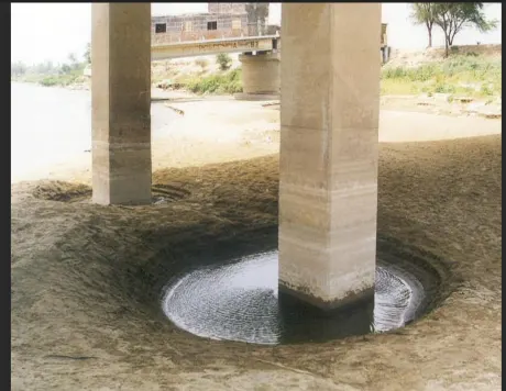
Calculation of scouring Depth.
Db = ((1.3 X Q)/L)
= 10.11 m
Ksf = 1
Dsm = `1.34 ((Db^2)/(ksF))^(2/3)`
=6.26 m
Maximum depth of scour for design of foundation,
For Abutment,
= 1.27 X dsm
= 1.27 X 6.26
= 8.41
Depth of foundation below foundation.
= 8.41 - HFL
= 8.41 - 3
= 5.41 m
For Pier,
= 2 X dsm
= 2 X 6.26
= 12.52
Depth of foundation
= 12.52 - HFL
= 12.52 - 3
= 9.52 m
Basic Design Data:-
For Span and Cross-Section:-
| Sl No | Items | Quantity | Units |
| 1 | C/c of exp joint | 15 | m |
| 2 | C/c of bearing | 14 | m |
| 3 | Dist. Of bearing to exp joint | 0.5 | m |
| 4 | Total Deck width | 12.5 | m |
| 5 | Carriage width | 8.5 | m |
| 6 | Footpath width (One Side) | 1.5 | m |
| 7 | Width of Crashbarrier ( Right Side) | 1 | m |
| 8 | Width of Crashbarrier ( Left Side) | 1 | m |
Superstructure Details:-
| Sl No | Items | Quantity | Units |
| 1 | No of girder | 1 | Nos. |
| 2 | Depth of superstructure | 2.7 | m |
| 3 | Wearing coat thickness | 0.065 | m |
| 4 | Dist. of FRL | 10.9 | m |
| 5 | Bearing thickness | 0.065 | m |
| 6 | Pedestal thickness | 0.25 | m |
Level:-
| Sl No | Items | Remarks | Quantity | Unit |
| 1 | Height of Substructure | Assumption | 6 | m |
| 2 | Finish road Level | FRL | 100 | m |
| 3 | Bearing Level | BRG | 97.3 | m |
| 4 | Pier Cap Top level | 97.235 | m | |
| 5 | Pier Cap Bottom level | 96.235 | m | |
| 6 | Ground Level | GL | 93.5 | m |
| 7 | High Flood Level | HFL | 95.9 | m |
Materials:-
| Sl No | Items | Remarks | Values | Others |
| 1 | Concrete Grade | fck M | 35 | KN/m2 |
| 2 | Design strength of concrete | fcd | 15.63 | KN/m2 |
| 3 | Steel Grade | fyk Fe | 500 | KN/m2 |
| 4 | Design strength of steel | fyd | 434.78 | KN/m2 |
| 5 | Density of RCC | 2.5 | KN/m3 | |
| 6 | Density of WC | 2.2 | KN/m3 | |
| 7 | Coefficient of thermal expansion of concrete. | 1.2 | E-05/ c |
Abutment Dimensions:-
| Sl No | Particulars | Quantity | Unit |
| 1 | Length of abutment at top | 2.52 | m |
| 2 | Length of abutment at bottom | 1.5 | m |
| 3 | Width of the abutment | 12.5 | m |
| 4 | width of the median wall | 3.5 | m |
| 5 | Thickness of the stem | 1.5 | m |
| 6 | Thickness of the Dirtwall | 0.3 | m |
| 7 | Depth of abutment cap | 0.5 | m |
| 8 | Depth of abutment cap uniform | 0.5 | m |
| 9 | Return Wall thickness | 0.5 | m |
Parameters of the Soil:-
| Sl No | Items | Values | Units |
| 1 | Angle of shear resistance | 30 | deg. |
| 2 | Density of dry backfill | 2 | t/m3 |
| 3 | Density of submerged backfill | 1 | t/m3 |
| 4 | Net SBC | 25 | t/m3 |
| 5 | Gross SBC (LWL) | 33.42 | t/m3 |
| 6 | Gross SBC (HFL) | 27 | t/m3 |
| 7 | Live Load surcharge | 1.2 | m |
| 8 | Type of soil | median | soil |
| 9 | Coefficient of friction | 0.5 |
Substructure:-
Abutment
| Particulars | Value | Items |
| Length ( Longitudinal ) | 12.5 | m |
| Length ( Transverse ) | 2.52 | m |
| Height | 0.5 | m |
| Volume | 15.75 | m3 |
| Weight | 39.375 | t |
| Trapezoidal Part | ||
| Particulars | Value | Units |
| Top Length | 12.5 | m |
| Bottom Length | 12.5 | m |
| Top width | 2.52 | m |
| Bottom width | 1.5 | m |
| Height | 0.5 | m |
| Volume | 12.5625 | m3 |
| Weight | 31.40625 | t |
| Total weight of pier cap | 70.78125 | t |
| Abutment Shaft | ||
| Particulars | Value | Units |
| Length ( Longitudinal ) | 12.5 | m |
| Length ( Transverse ) | 1.5 | m |
| Height | 6 | m |
| Volume | 112.5 | m3 |
| Weight | 281.25 | t |
| Material | Basic Combination | Seismic Combination |
| Concrete | 1.5 | 1.5 |
| Steel | 1.15 | 1.15 |
Loadings on the Superstructure:-
| DL of Superstructure | ||
| Particulars | Values | Units |
| Total weight of superstructure | 228.21 | t |
| Reaction | 114.105 | t |
| Total reaction on abutment | 114.105 | t |
| Distance betwwen bearing & CL of abutment shaft | 0 | m |
| Longitudinal movement | 0 | t-m |
| Transverse ecentricity of Dl from C/l of abutment | 0 | m |
| Transverse Movement | 0 | t-m |
| SIDL -1(Excluding WC) | ||
| Crash barrier weight | 84.375 | t |
| Railing weight | 0 | t |
| Foothpath / service weight | 0 | t |
| Total reaction on abutment | 42.1875 | t |
| SIDL-2 ( WC) | ||
| Load intensity due to wearing course | 0.22 | t |
| DL of wearing course | 18.24 | t |
| Total reaction on abutment | 9.12 | t |
Force Summary at Footing Level:-
| Load Item | P | ML | MT | HL | HT | |
| t | t-m | t-m | t-m | t-m | ||
| Dead Load | 114.105 | 0 | 0 | 0 | 0 | |
| SIDL 1 | 42.185 | 0 | 0 | 0 | 0 | |
| SIDL 2 | 9.12 | 0 | 0 | 0 | 0 | |
LIVE LOADS
For 1 Lane 70R Wheeled
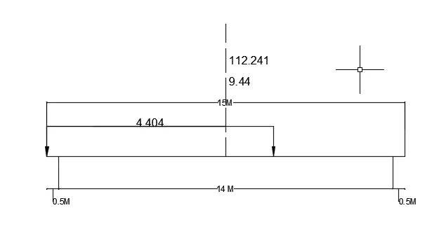
| Live Load reaction | |||
| Particulars | Value | Unit | Remarks |
| Total live load | 92 | t | |
| No of lanes | 2 | Nos. | |
| % reduction in live load | 0 | % | |
| impact factor - | 1.22 | As per IRC 6 | |
| Total load with imact | 112.24 | ||
| Ra | 80.94 | t | |
| Rb | 31.29 | t | |
| Vertical reaction on the abutment | 84.55 | t | |
| Breaking force | 16.91 | t | 20 % of Ra |
| Total horizontal force at abutment | 8.455 | t | Fh/2 |
| Transverse eccentricity | 3.155 | m | |
| Transverse movement | 266.755 | t-m | |
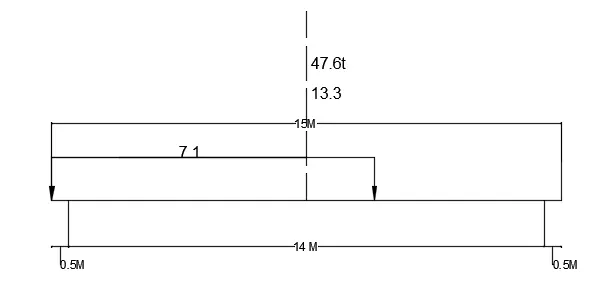
| Live Load reaction | |||
| Total live load | 38.8 | t | Remarks |
| No of lanes | 2 | nos | |
| % reduction in live load | 0 | % | reduction |
| Impact factor - | 1.22 | As per IRC 6 | |
| Total load with imact | 47.336 | ||
| Ra | 25.16 | t | |
| Rb | 22.34 | t | |
| vertical reaction on the abutment | 28.45 | t | |
| Breaking force | 5.69 | t | 20 % of Ra |
| Total horizontal force at abutment | 2.845 | t | Fh/2 |
| Transverse eccentricity | 4.5 | m | |
| Transverse movement | 128.025 | t-m | |
Force Summary at Footing Level
| Load Item | P | Load (Min) | ML | MT | HL | HT | |
| t | t | t-m | t-m | t-m | t-m | ||
| Class 70 R vehicle | 84.55 | 31.29 | 84.55 | 266.76 | 8.445 | 0 | |
| Class A vehicle | 28.45 | 22.34 | 28.45 | 128.025 | 2.845 | 0 | |
Earth Pressure Load:-
| Horizontal force due to earth pressure on abutment acts in L-L direction | |||
| Abutment Width | b | 12 | m |
| Coefficient of Horizontal Earth Pressure | Kah | 0.279 | |
| Coefficient of Vertical Earth Pressure | Kav | 0.102 | |
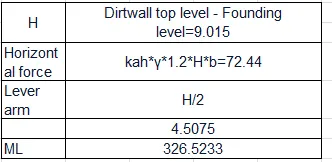
| H | Dirtwall top level - Founding level | |||
| 9.015 | ||||
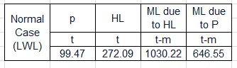
| Horizontal force in longitudinal Direction | 0.5*kah*γ*H2*b | |||
| 272.09 | ||||
| Lever arm from bottom of the foundation | 0.42*H | |||
| 3.7863 | ||||
| ML | 1030.214367 | |||
| Abutment portion | |
| Vertical Force | 99.47 |
| Lever arm from toe | 6.5 |
| ML | 646.555 |
Force Summary at the bottom of foundation:-
LIVE LOAD SURCHARGE:-
Normal Case
Abutment Portion:-(@bottom level)
Force Summary:-
| LWL | p | HL | ML due to HL |
| t | t | t-m | |
| 0 | 72.44 | 326.523 |
Calculation Of Backfill Weight
| Width of backfill in transverse direction | 12 | m |
| Portion a | ||
| Weight | 991.8 | t |
| Horizontal Lever Arm from toe in L-L dir. | 5.26 | t-m |
| Portion b | ||
| Weight | 52.6 | t |
| Horizontal Lever Arm from toe in L-L dir. | 2.86 | t-m |
| Portion c | ||
| Weight | 1.1 | t |
| Horizontal Lever Arm from toe in L-L dir. | 2.91 | t-m |
| Portion d | ||
| Weight | 38.64 | t |
| Horizontal Lever Arm from toe in L-L dir. | 5.9 | t-m |
Force Summary:-
| Portion | Weight | Lever arm | ML |
| t | m | t-m | |
| a | 991.8 | 5.26 | 5216.87 |
| b | 52.6 | 2.86 | 150.436 |
| c | 1.1 | 2.91 | 3.201 |
| d | 38.64 | 5.9 | 227.976 |
Total Force Acting on the Foundation:-
| Loads | P MAX | P MIN | ML | MT | HL |
| Dead load | 114.11 | 114.11 | 0 | 0 | 0 |
| SIDL | 42.19 | 42.19 | 0 | 0 | 0 |
| SIDL (Wearing Coat) | 9.12 | 9.12 | 0 | 0 | 0 |
| Class 70 R vehical | 84.55 | 31.29 | 84.55 | 266.76 | 8.445 |
| Class A vehical | 28.45 | 22.34 | 28.45 | 128.025 | 2.845 |
| Earth pressure | 99.47 | 99.47 | 1030.22 | 0 | 272.09 |
| Live load surcharge | 0 | 0 | 326.53 | 0 | 72.44 |
| Weight of Substructure | 384.71 | 384.71 | 315.45 | 0 | 0 |
| Weight of soil above tie | 1084.14 | 1084.14 | 5598.48 | 3604 | 16.93 |
| Total | 1846.74 | 1787.37 | 7383.68 | 3998.79 | 372.75 |
2) What is zero shear point and if there is more scour at region what will be the effect of that on zero shear point?
The point of zero Bending Moment also known as point of contraflexure which occurs at two points in between the supports of continuous beams and slabs. Point of zero shear is that point where is Shear Force is zero. At this point +ve BM is maximum. -Ve BM is maximum where SF changes its sign.
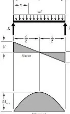
Passive earth pressure shall be considered when there will more scour also deep excavation needs to take place will be different and hence point of zero shear will be lower than normal.
Soil Liquifaction:-
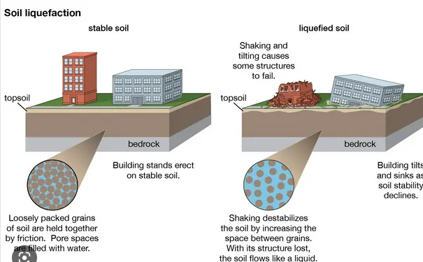
Liquefaction takes place when loosely packed, water-logged sediments at or near the ground surface lose their strength in response to strong ground shaking. Liquefaction occurring beneath buildings and other structures can cause major damage during earthquakes
Liquefaction is a phenomenon in which the strength and stiffness of a soil is reduced by earthquake shaking or other rapid loading. Liquefaction and related phenomena have been responsible for tremendous amounts of damage in historical earthquakes around the world
Effects of Liquifaction on Foundation:-
- The uneven settlement of a raft foundation may damage it.
- The cracks in the foundation are dangerous for the structure’s safety.
- A cracked foundation fails to distribute the load evenly on the ground.
Remeddies:-
The most common way of preventing the occurrence of liquefaction are foundation soil improvement methods.
One type of improvement is to replace the susceptible soil with the appropriate amount of gravel.
A more favourable form of the granulometric soil curve in a narrower location is obtained in this way.
Liquefaction hazards can be reduced by increasing the drainage ability of the soil.
If the porewater within the soil can drain freely, the build-up of excess pore water pressure will be reduced.
Drainage techniques include installation of drains of gravel, sand or synthetic materials.