Project 1
AIM OF THE EXPERIMENT:-
Calculate the dead load , IRS live loads , Earth pressure load , wind load and seismic loads for the bridge structure at Ahmedabad Metro rail project shown in the figure. Assume the unit weight of soil as 18 kN/m3 . Use IS 875 code book for finding the Basic wind speed at the site location. Use IS 1893 code book for determining the seismic zone. Assume suitable data.
Model the bridge structure in Staad Pro and Apply all the calculated loads.
THEORIES:-
IRS- INDIAN RAILWAYS STANDARD
- IRS code were developed by Indian Railways for the purpose of Design and Construction of Railway related structures.
- Types of IRS Loads for Design of Bridge Includes:-
- Metro rail Loadings
- Broad gauge Loadings
- Electric Train
- Gauge A & Gauge B Loadings
- Earth Pressure:- Earth pressure is the lateral pressure exerted by the soil on a shoring system. It is dependent on the soil structure and the interaction or movement with the retaining system
- Types of Earth Pressure:-
- Earth Pressure at Rest
- Active Earth Pressure
- Passive Earth Pressure
- Active Earth Pressure:- The minimum value of lateral earth pressure exerted by soil on a structure, occurring when the soil is allowed to yield sufficiently to cause its internal shearing resistance along a potential failure surface to be completely mobilized
- Passive Earth Pressure:- Passive pressure is a condition in which the retaining system exerts a force on the soil.
- Ka=(1-sinφ/1+sinφ)
- Kp=(1+sinφ/1-sinφ) where, φ is the angle of repose, and Ka and Kp are the Co-efficient of earth pressure
- Angle of Repose- The angle that the plane of contact between two bodies makes with the horizontal when the upper body is just on the point of sliding
- Earth Pressure Formula-ψh
- Wind Zones in India
- Zone 1
- Zone 2
- Zone 3
- Zone 4
- Zone 5
- Zone 6
- Vz=Vb x k1 x k2 x k3 x k4
- There ara 4 seismic zones in India, they are
- Zone 2
- Zone 3
- Zone4
- Zone 5
DATA GIVEN:-
Site location- Ahmedbad
Type of Construction- Underground Metro
Seismic Zone- Zone3-0.16
Unit weight of soil-18Kn/m3
PROCEDURES:-
- STEP-1:-
Download and open the given project drawing and recheck it by entering by duplicate nodes, duplicate members etc.
- STEP-2:-
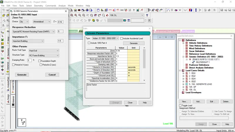
- Go to Seismic Defination,
- Click on add
- Select IS-1893:2002-2005
- Click on generate
- Select area city as Ahmedabad
- Response Reduction as SMRF
- Importance factor as Important Building as 1.5
- Soil Type as Hard soil
- Structure type as RC Frame Building
- Click on generate
- STEP 3:-
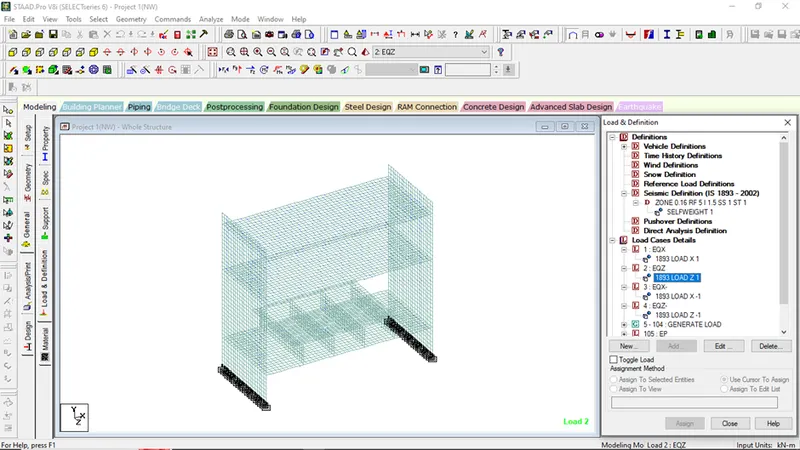
Go to load case details
Rename loading title as EQX+,EQZ+,EQX-,EQZ-
Select EQX+,
Click add
Select seismic loads
Click factor direction in x direction as 1
Select EQZ+,
Click add
Select seismic loads
Click factor direction in Z direction as 1
Select EQZ-,
Click add
Select seismic loads
Click factor direction in Z direction as -1
Select EQX-,
Click add
Select seismic loads
Click factor direction in X direction as -1
- STEP 4:-
- IRC LIVE LOAD (IRC metro loading)
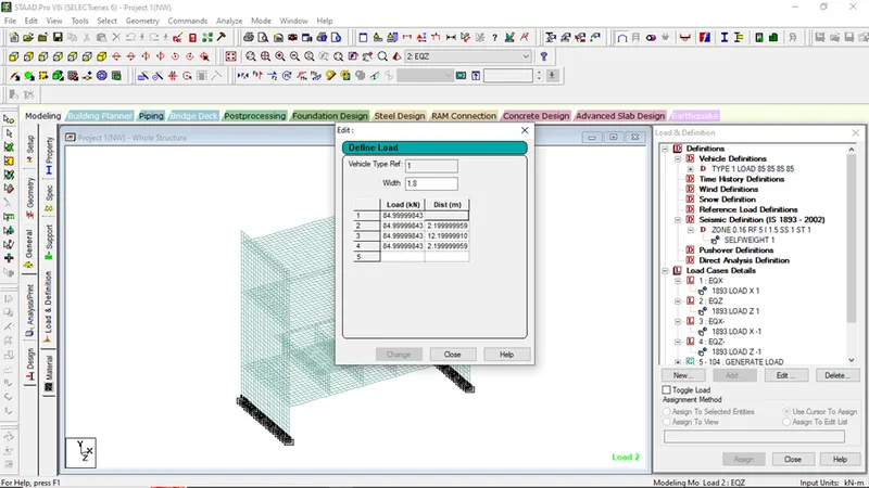
Go to vehicle definations
Select vehicle width as 1.8
Axle loading of metro =170KN
Wheel loading=170/2=85KN
|
85 |
|
|
85 |
2.2 |
|
85 |
12.2 |
|
85 |
2.2 |
Select add
Go to Load Case Details:-
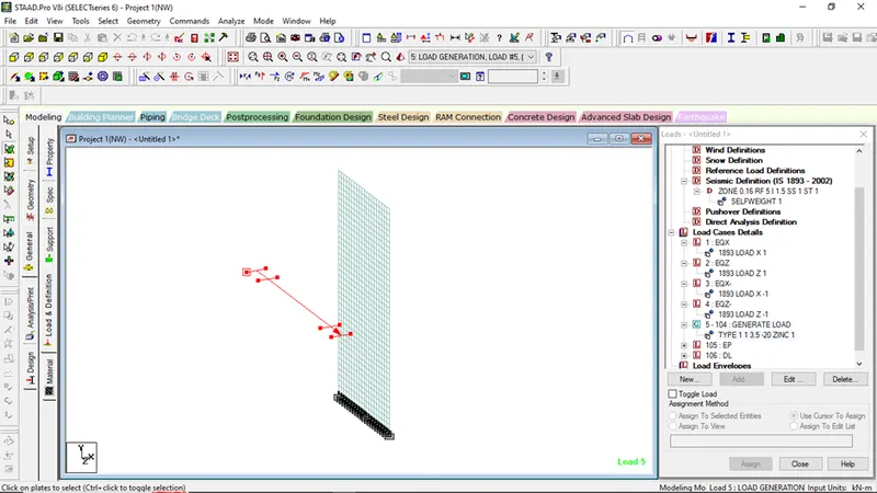
Select Load Generation
No. of loads to be generated=100
Select x,y,z plane where the initial point of load will be acted and the increment axis
- STEP 5:-
- For Earth Pressure Loads,
Select outer wall and new view that
Since it is an underground structure,
Unit weight of soil =18kn/m3
Height of the wall = 20m
Ka=1/3
EP=1/3XψXH
EP=1/3*18*20=120KN/M2
Select on plate loads
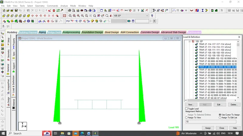
Click on Hydrostatic
Click on plate elements
Give the loading values
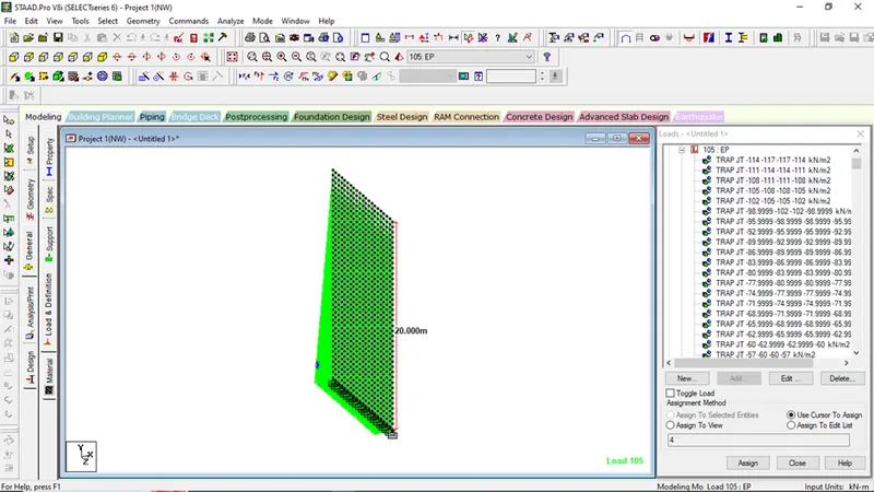
Similarly, apply it to another side of wall
And our EP load is completed
- STEP 6:-
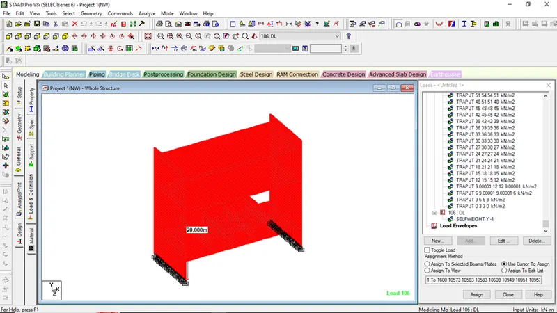
Application of DL in STAAD
Go to load case details
Rename load title as DL
Click on add
Select self weight
Select factor Y,-1
Click on add
Assign to view
Our application of loadings are done
Go to Analysis and Prrint
Select no print
Run Analysis on Analyze menubar
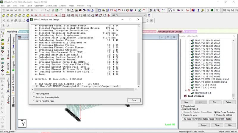
Now go to the Post Processing mode for getting the maximum SF, BM and deflection
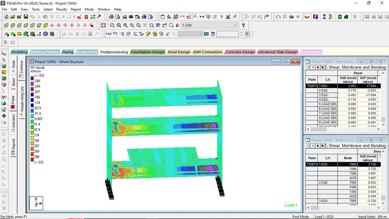
Fig showing plate contours on MXY ON EQX+
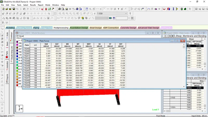
Fig showing maximum bending on plate elements
Fig showing maximum shear on plate elements
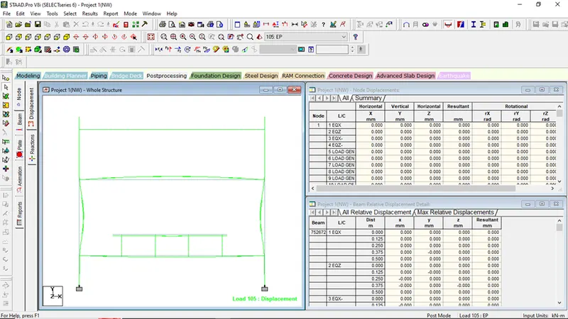
Fig showing Displacement on Earth Pressure