Week 1 Challenge
AIM OF THE EXPERIMENT:-
To Calculate the Dead Load of the Box Girder given in the above figure and apply it in Staad Pro. and perform analysis.
SOFTWARE REQUIRED:-
Staad Pro.
THEORY:-
Deadload:-
A constant load in a structure (such as a bridge or building) that is due to the weight of the members, the supported structure, and permanent attachments or accessories.
Components of Bridges:-
- Sub-structure
- Super-structure
Sub-structure:-
- Pile/Well Foundation
- Pile Cap/Well Cap
- Pier
- Abutment
- Wing Walls
- Pier Cap
- Pedestal
- Bearing
Super-structure:-
- Girder
- Deck Slab
- Truss
- Parapet
MATHEMATICAL CALCULATION:-
Data Given:-
Width of the Bridge Deck=10.2m or 10200mm
Span of the Bridge=12m or 12000mm
Pier Size=2.5m dia.
Seismic Zone=IV
Wind Speed=47kmph
Unit Weight of soil=19KN/m^3
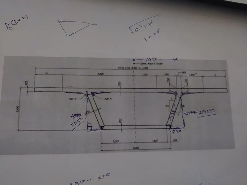
CALCULATING "A"
According to the Figure,
Since, width of the bridge deck=10.2m or 10200mm
We have the Centre Line, so the Bridge deck is divided into two equal parts
Hence, Width=10200/2=5100mm
Now "A"=5100-4200=900mm
DEADLOAD CALCULATION:-
Since it is a box girder with inclined angle, we have to divide the whole structure into number of rectangles and triangles
| Sl.No | Type of Figure | Length/Base(m) | Thickness/Height(m) | Area(m^2) | Weight(KN/m) Area*Density of Conc. i.e. (Area*25) |
| 1 | Rectangle | 10.2 | 0.225 | 2.295 | 57.375 |
| 2. | Rectangle | 4.02 | 0.200 | 0.804 | 20.1 |
| 3. | Rectangle | 2.115 | 0.250 | 0.528 | 13.21 |
| 4. | Rectangle | 2.115 | 0.250 | 0.528 | 13.21 |
| 5. | Triangle | 1.2 | 0.125 | 0.075 | 1.875 |
| 6. | Triangle | 1.2 | 0.125 | 0.075 | 1.875 |
| 7. | Triangle | 1.370 | 0.125 | 0.085 | 2.14 |
| 8. | Triangle | 1.370 | 0.125 | 0.085 | 2.14 |
Hence, The total was found out to be=111.925KN/m
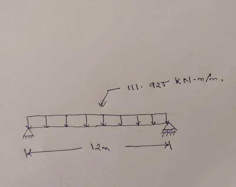
STAAD PRO. METHODOLOGY
- Staad Pro. V8i Software was opened.
- A new Folder was created on PC.
- On Staad Pro. Check on New Project
- Set Unit and Force Unit as Metre and Kilo Newton.
- Check on Space
- Mention the Project Name and the Project Location
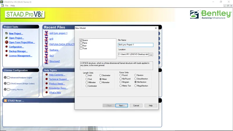
- Click on Next
- Check on Add Beam
PROCEDURE:-
- Let us Assume, the height of Pier=10m
- The entire structure will be modelled as SLD(SINGLE LINE DIAGRAM)
- In Geometry, The model was prepared as per the requirement
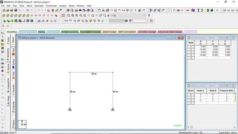
- For, Creating Dummy Beam,i.e. the density of material will be "0"
Go to General----------Material-------------Create-------------Density=0
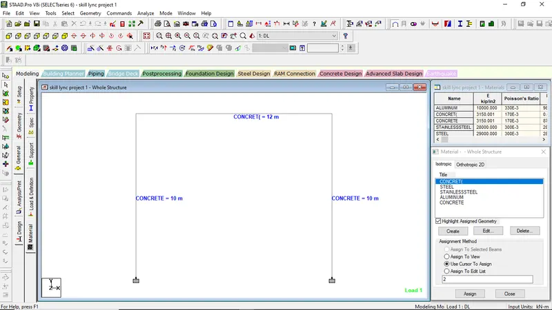
- Property Assign
FOR PIERS
- Go to General,
- Select Property,
- Select Define,
- Select Circle,
- Mention Yd value=2.5m (Data Given)
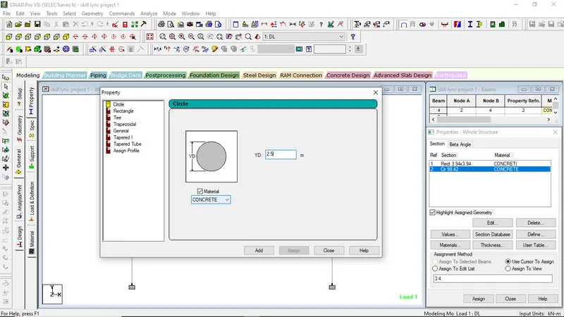
FOR BOX GIRDER
- Go to General,
- Select Property,
- Select Define,
- Select Rectangle,
- Mention Yd and Zd value=0.1m respectively
- also assign the dummy material to the girder element
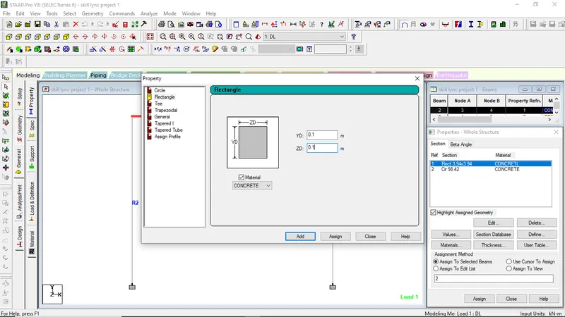
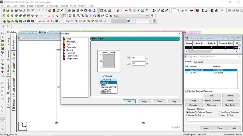
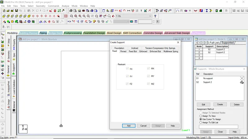
SUPPORT CONDITION:-
- Go to General
- Click on Support
- Click on Create
- click on Fixed and then Ok
- Click on the support that you have prepared and assign it on the respective base.
APPLICATION OF LOADINGS:-
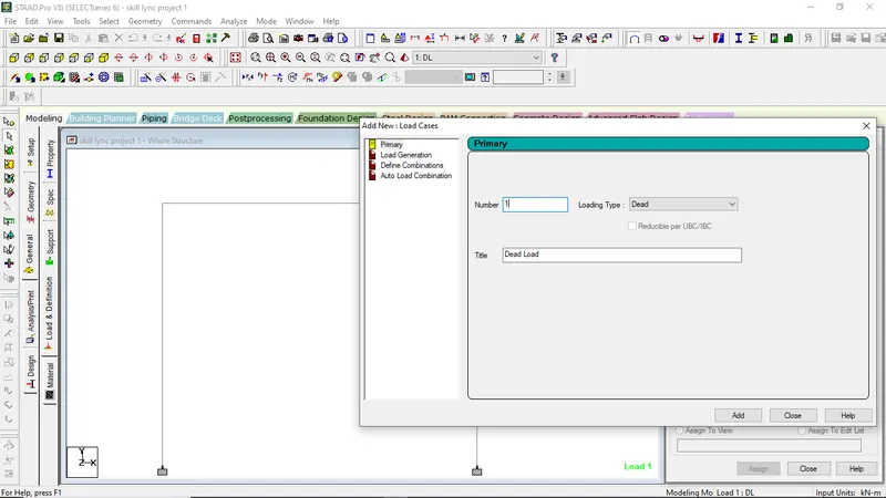
- Go to General
- Click on Loads and Defination
- Select on Load Case Details
- Click Add
- Select Loading Type as Dead
- In Title, Type DL
- Then Add
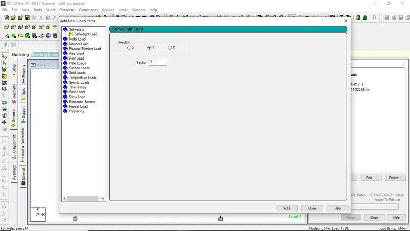
- Click on Load Case 1 "DL"
- click on Add
- Select self weight
- Click on Add
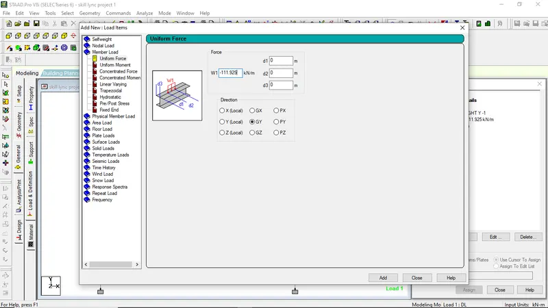
- Click on Member load, click on Uniform Force and give the Force value -111.925KN/m (-ve value because force is acting in downward direction)
- Then Close
ASSIGN OF LOADS
- Click on self weight
- Click on assign to view
- ok
- Now Click on UNI GY -111.925KN/m and assign it on Girder.
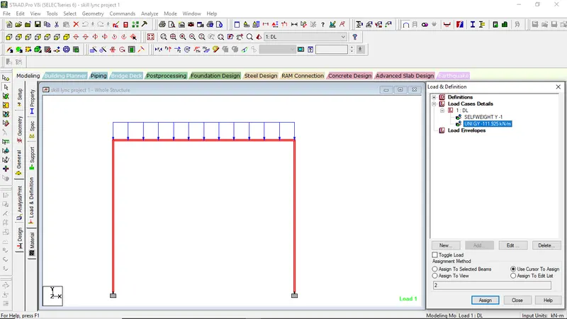
ANALYSIS OF STRUCTURES
- Go to Analysis Print
- Select on No Print
- Go to Analyze on Main Menu
- Select Run Analysis
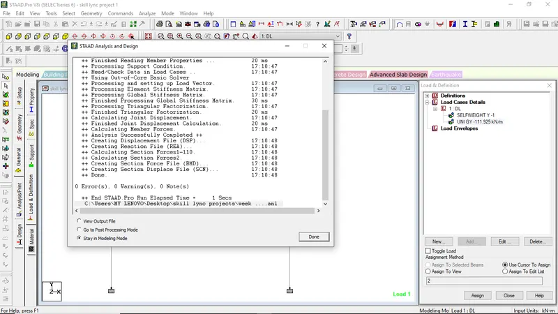
POST-PROCESSING
In Post Processing we can find out maximum displacement, Shear , Moment values etc
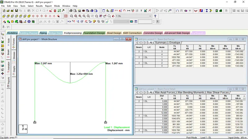
Fig MAXIMUM DISPLACEMENT
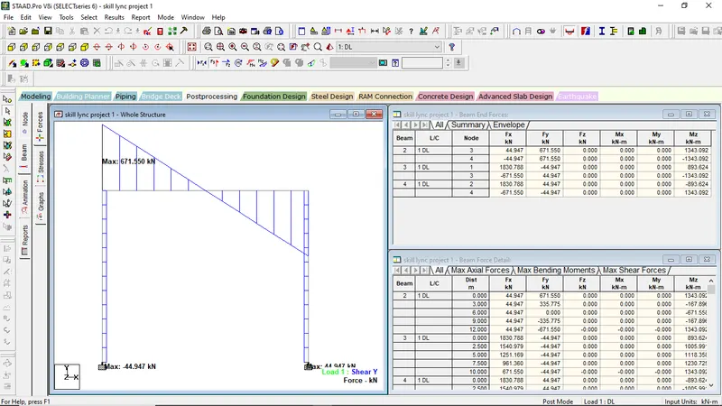
Fig MAXIMUM SHEAR FORCE
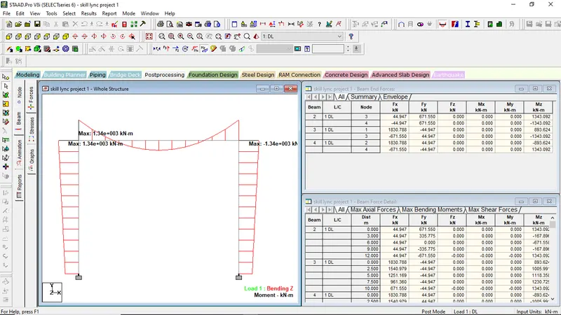
Fig MAXIMUM BENDING MOMENT