Week 4 Challenge
AIM OF THE EXPERIMENT:-
To calculate the Earth Pressure acting on the abutment of the wall and perform analysis on Staad Pro.
THEORIES:-
- ABUTMENT: Abutment are the end supports of the bridge or any culvert which supports the lateral loads or pressure that are acting on the bridge.
- Earth Pressure:- Earth pressure is the lateral pressure exerted by the soil on a shoring system. It is dependent on the soil structure and the interaction or movement with the retaining system
- Types of Earth Pressure:-
- Earth Pressure at Rest
- Active Earth Pressure
- Passive Earth Pressure
- Active Earth Pressure:- The minimum value of lateral earth pressure exerted by soil on a structure, occurring when the soil is allowed to yield sufficiently to cause its internal shearing resistance along a potential failure surface to be completely mobilized
- Passive Earth Pressure:- Passive pressure is a condition in which the retaining system exerts a force on the soil.
- Ka=(1-sinφ/1+sinφ)
- Kp=(1+sinφ/1-sinφ) where, φ is the angle of repose, and Ka and Kp are the Co-efficient of earth pressure
- Angle of Repose- The angle that the plane of contact between two bodies makes with the horizontal when the upper body is just on the point of sliding
- Earth Pressure Formula-Kaψh
DATA GIVEN:-
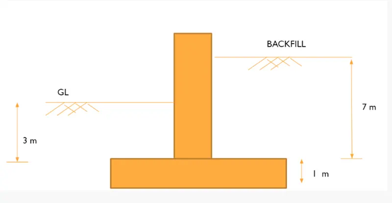
Length of Abutment wall=5m
Height of the wall=10m (say)
Water Table at GL=3m
Height of the Backfill=7m
Assume that angle of repose = 30deg.
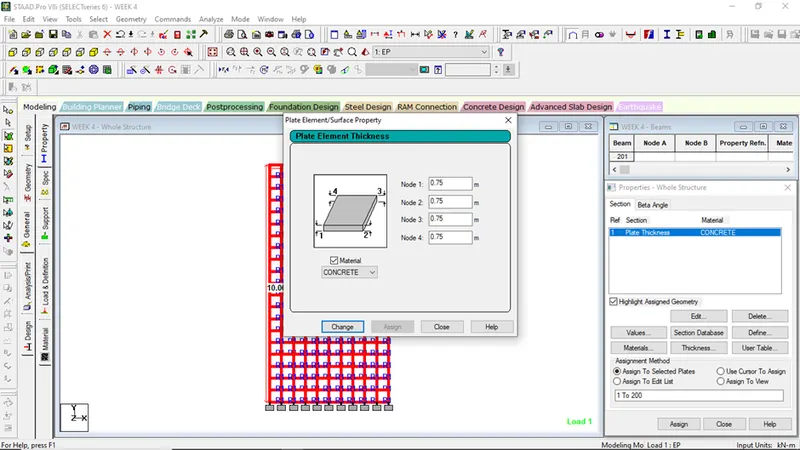
Width of the Abutment = 750mm
Unit weight of soil= 18KN/m3
Unit weight of water= 10KN/m3
CALCULATIONS:-
- For 7m backfill portion
EP= Ka.ψ.h
Ka=(1-sinφ/1+sinφ)
=(1-sin30)/(1+sin30)=1/3
EP= (1/3)X18X7=42KN/m2
- For 3m Hydrostatic Pressure or water Pressure
WP= ψW.h
10X3=30kn/m2
Procedures in Staad Pro.
- Step 1-
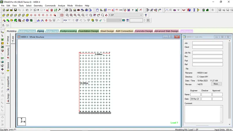
Create a plate elements as per given question
i.e.5m*10m
Mesh it into unit plate dimension 0.5*0.5m
- Step 2-
Assign the material and thickness properties
- Step 3:-
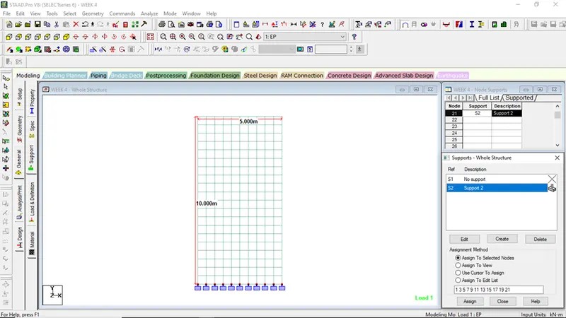
Assign the support Condition as fixed support
- Step 4:-
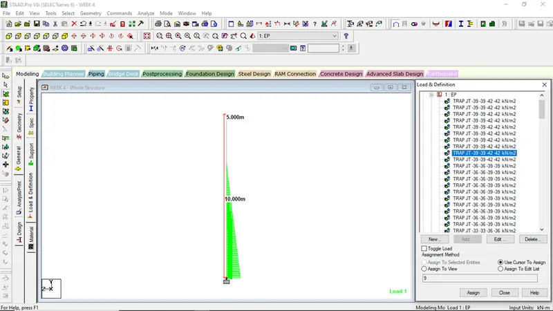
Application of Earth Pressureloadings
- Select the right side view
- Go to the load cases details
- Select on Add button
- Rename Title as Eatrh Pressure
- Now select on Earth Pressure and click on Add
- Go to the plate Loads
- Select on Hydrostatic
- Select the Plate elements
- Now put the value of loads in W1
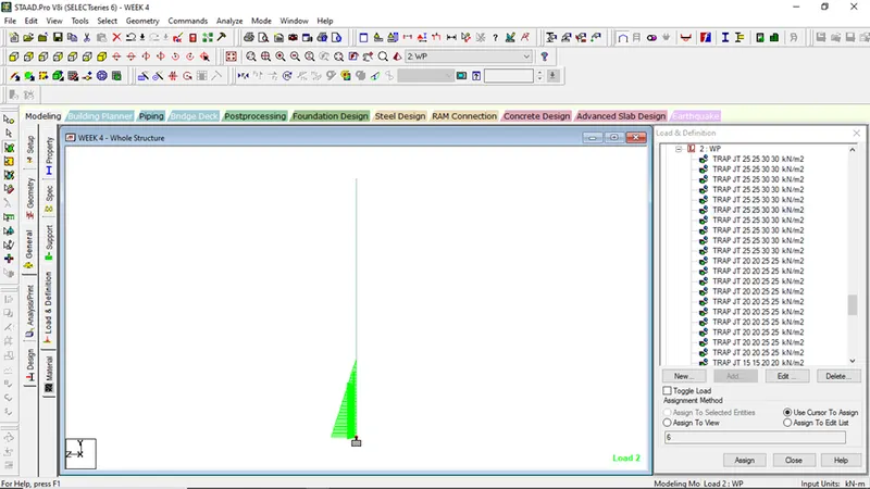
Application of Water Pressure loadings
- Select the right side view
- Go to the load cases details
- Select on Add button
- Rename Title as Water Pressure
- Now select on Water Pressure and click on Add
- Go to the plate Loads
- Select on Hydrostatic
- Select the Plate elements
- Now put the value of loads in W1
- Step 5:-
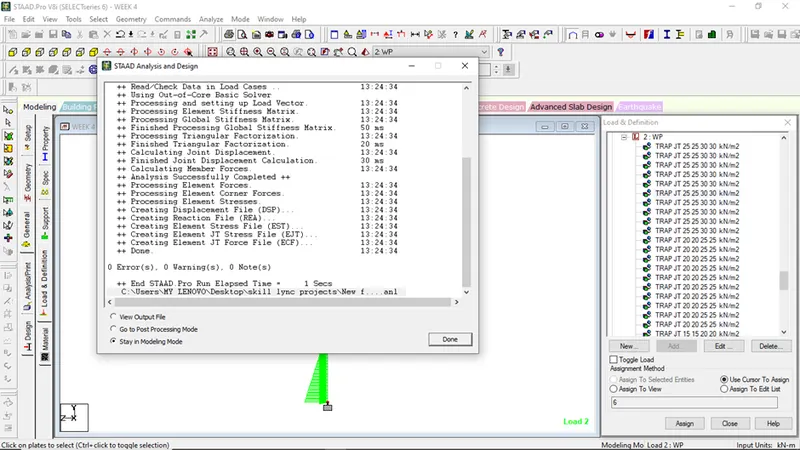
Go to Analysis and Print
Select on Run Analysis on Analyze Menu bar
Now go to the Post Processing mode, for getting the maximum bending moment, displacement, support reactions etc
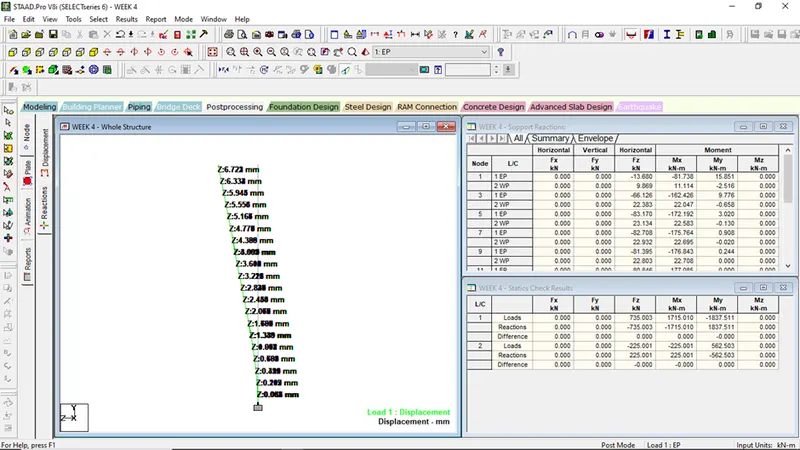
Figure showing the displacement on EP
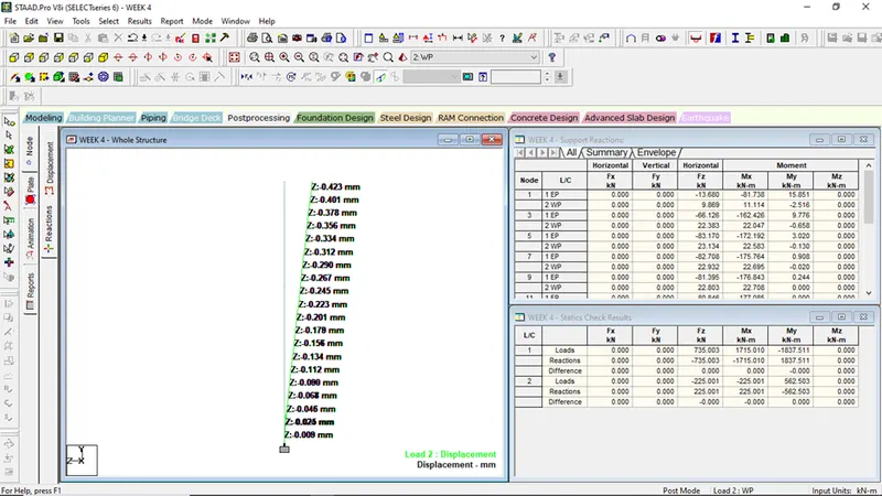
Figure showing the displacement on WP
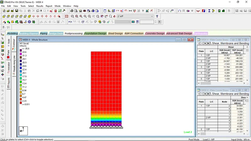
Fig showing plate contours for My local WP
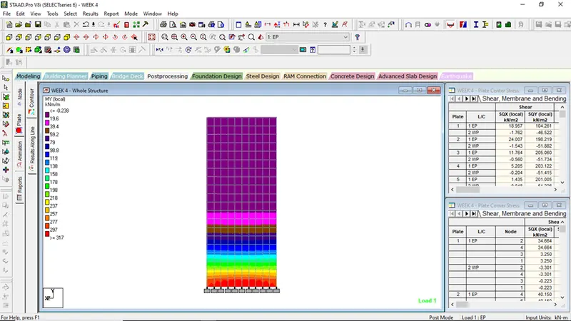
Fig showing plate contours for My local WP
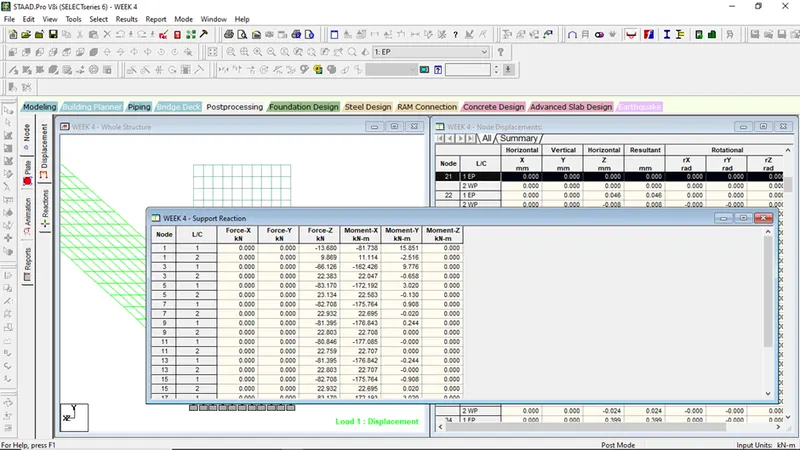
Fig showing Support Condition for Fy