Assignment 1
- Objecive: To perform 2D meshing on the given sheet metal componments using following quality criteria-
Target length: 5mm
Min length : 3.5mm
Max length : 7mm
Ignore all holes less than 5mm diameter.
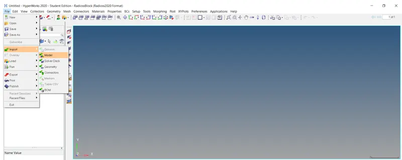
- Procedure: All the given files are .hm files. We will import them one by one and work on them individually. To import the .hm file, go to File > Import > Model.
.
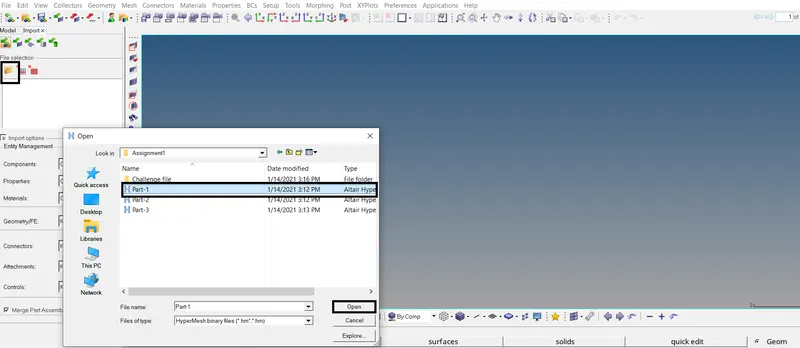
Click on select file icon. Navigate to the directory where the file is stored. Select the file and click Open. Then click on Import.
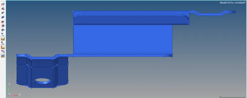
The file is now imported. But nothing is seen on the virtual screen. Press F to fit to scrren, so that the geometry fits to screen as seen below.
Now the next step is to perform geometry check to check for any errors in the geometry such as presence of any free edges, duplicate surfaces, missing surfaces etc. To quickly locate these errors, set the
Geometry color mode to By Topo. Now click on the Visualization icon. Uncheck everything expect Free edges and Non-Manifold edges. Now only free edges and Non-Manifold edges will be visible.
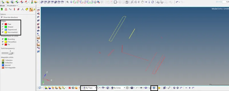
As seen above, there are few free edges and Non-Manifold edges in the geometry. Again check all the options, since we now know the locations of the errors in the geometry.
Zoom into locations of these error to fix them. As seen below, one of the surface has extra surface extending beyond required boundary. We can remove it by trimming the extra surface.

Go to Geom > Surface edit > trim with lines > with lines. In the surface selector, select the surface highlighted by black color and in the surface edge selector, select the surface edge highlighted by
white color. Set normal to surface. click on trim.
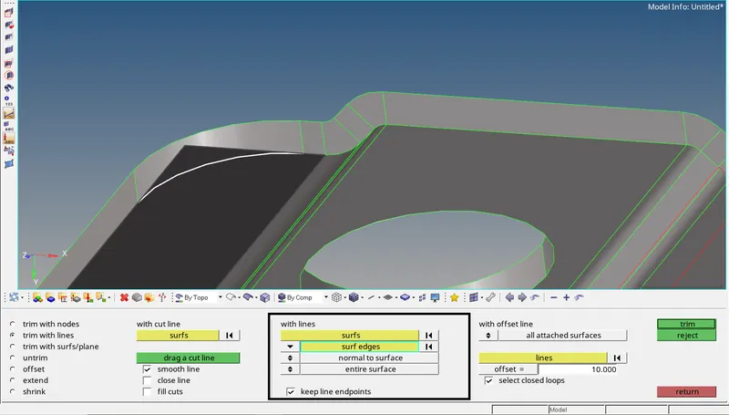
The surface will now be trimmed as seen below indicated by shared edge. Press F2 to go to delete panel. Select the trimmed surface and click on delete entity to delete the surface.
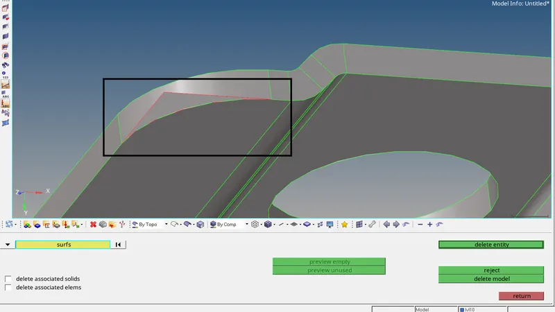
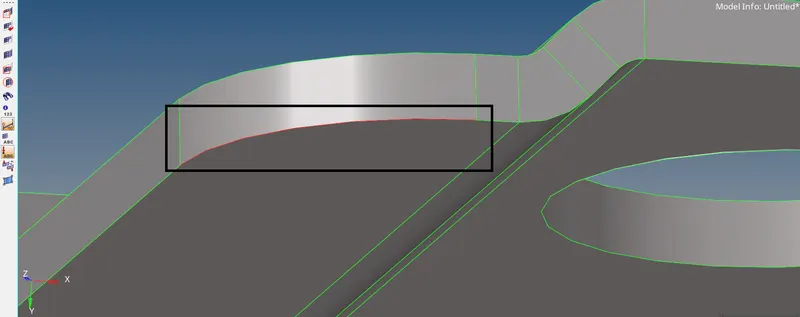
But still there is minor gap between the surfaces as seen above indicated by red line. To fix this free edge, go to quick edit panel. Press F11. Select Toggle edge. Set tolerance to 0.1
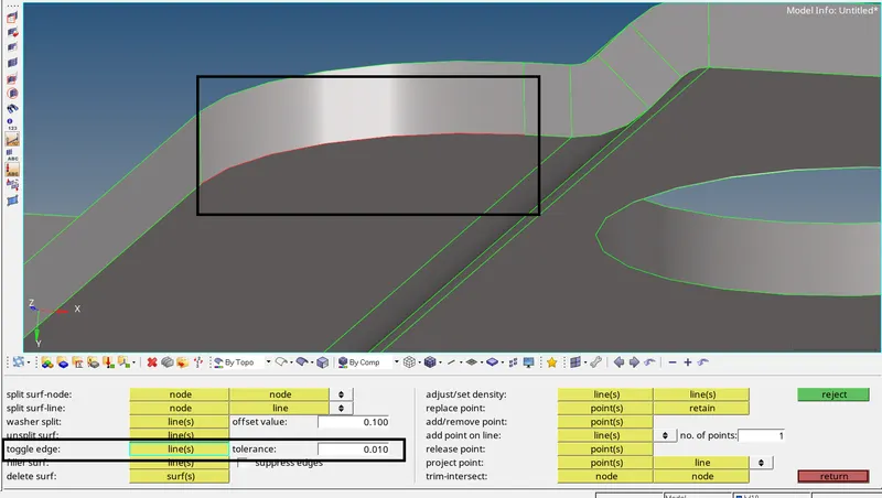
Click on the free edge so stich them together. The edges will be connected as seen below.
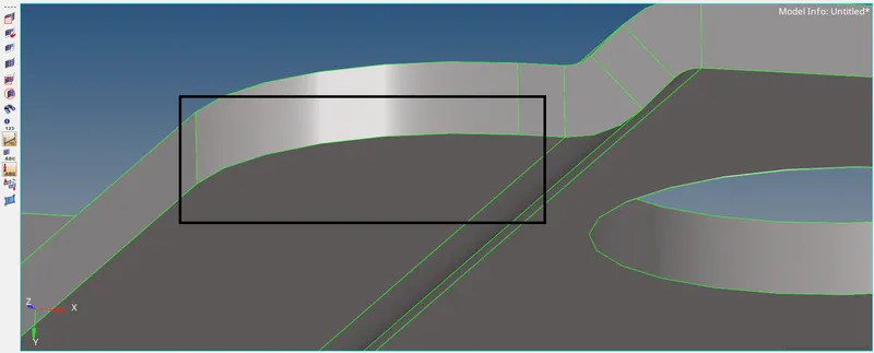
Repeat the same procedure for all the free edges in the model. After fixing the free edges, let us fix the missing surface issue in the geometry.
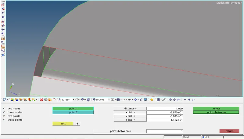
In this region, there is surface fillet missing. The distance between two points of the missing fillet is around 1mm. Since this distance is very small, the missing surface can be easily created using filler surf
option from the quick edit panel. This command will creat a curve surface between the missing surface. Go to Quick edit panel > Filler surf and click on any line of the free edge. The surface will be now
created as seen below.
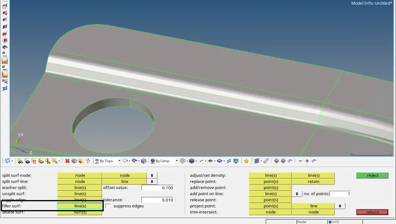
Now, there are no free edges in the model. Let us fix the Non-manifold edges.\
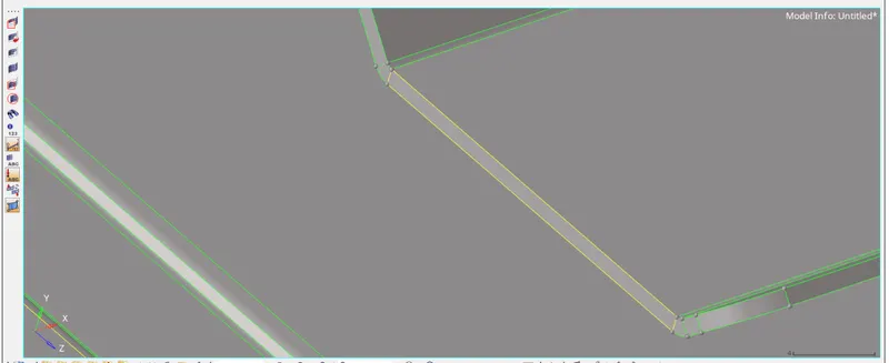
The Non-Manifold edge should not exist at the above seen place. The edge should be shared edge highlighted by green color, not yellow. No-Manifold edge here indicates presence of duplicate surface.
Go to delete panel and then delete the surface. Shared edge is now visible, indicating no presence of extra surface now.
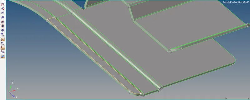
Repeat similar procedure for the other Non manifold edge. Now the geometry contains only shared edges and we can extract the mid surface. To extract the mid surface, go to Geom > midsurface >
auto midsurface. In the entity selector, select the displayed surface and click on extract. The midsurface will be now extracted in a new component.
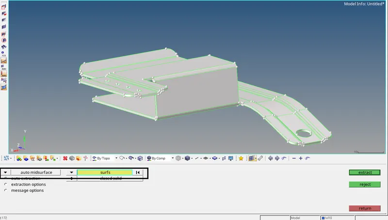
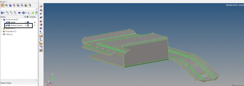
Now turn off the display for parent geometry from the model browser, so that only midsurface is visible. Before starting the meshing, we need to defeature the geomtery at some places, where the elements
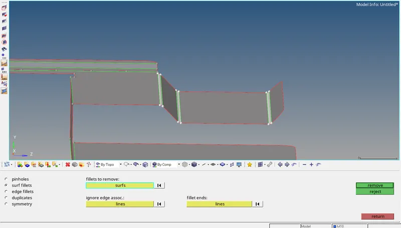
would fail for quality criteria. Let us remove all surface fillets less than 3.5mm, so that the elements won't fail for min lenght criteria.
Go to Geom > Defeature > surf fillets > find fillets by profile. Manually select the shown line profiles and click on find. The fillets will be now selected. click on remove. The fillets will be removed.
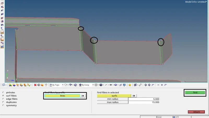
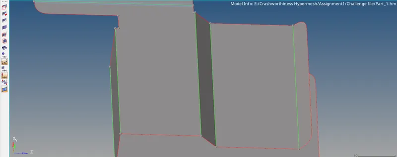
Toggle the shown feature lines. Though we will not be able to capture the geometry, the element quality for min length will not be comprosied.
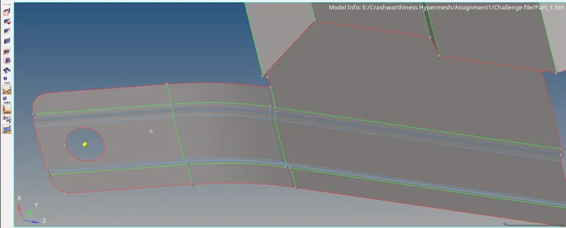
Below shown holes have diameeter less than 5mm, so we can remove them. Go to quick edit panel > Filler surf (check supress edges).
Click anywhere on the circumference of the circle. The hole will be filled with material and the shared edge will be suppressed.
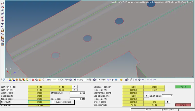
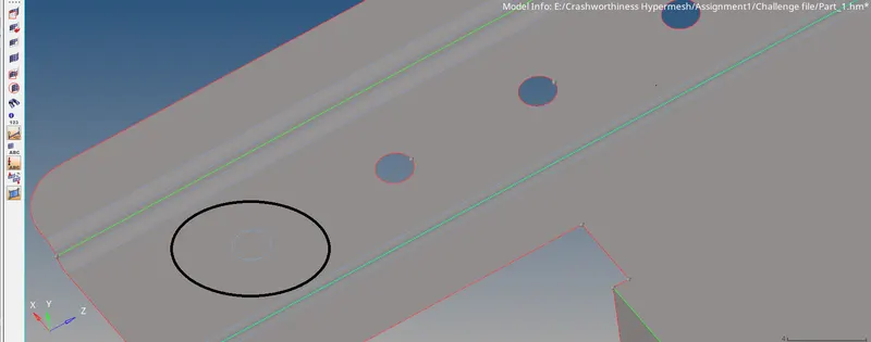
Repeat for all the holes having diameter less than 5mm. Also remove unwanted hot points. The component is now ready for meshing.
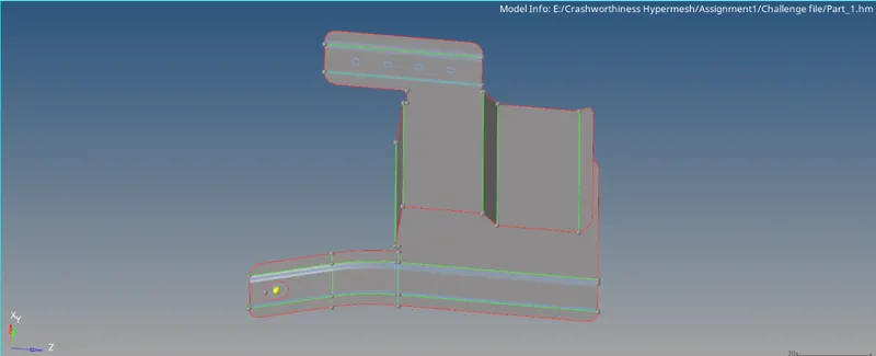
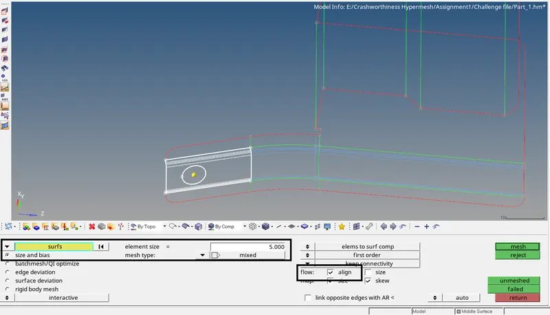
Go to 2D > automesh. Set entity selector to surfs. Enter element size =5 and keep mesh type as mixed. Check align option. Select the surface to be meshed and click on mesh. The surface will be meshed.
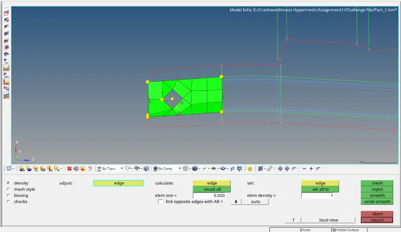
Similarly, mesh the remaining surfaces. Remesh wherever required to get better mesh flow and maintain quality criteria.
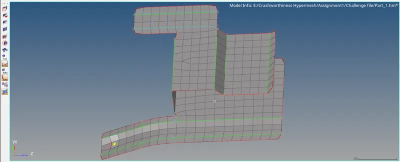
No failed elements are found for quality criteria. After meshing the component, check for any free edges between the elements. Go to Tools > edges. Set entity selector to elements. Select all elements and
click on find edges. The free edges will be extracted. Set the Geometry color mode to By Topo.
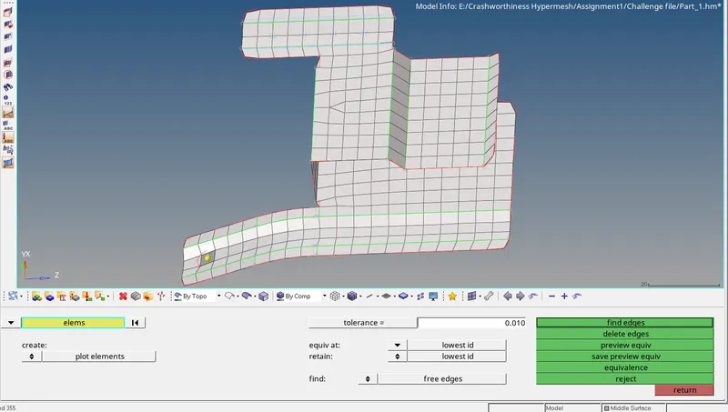
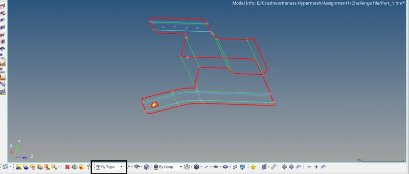
Free edges are found only at the outer bouandary as expected, indicating that there are no free elements and all the nodes of the FE's are connected. Now perform last important check left - the direction of
normal. To check the direction of normal, go to Tool > normals. Select all the elements and click on display.
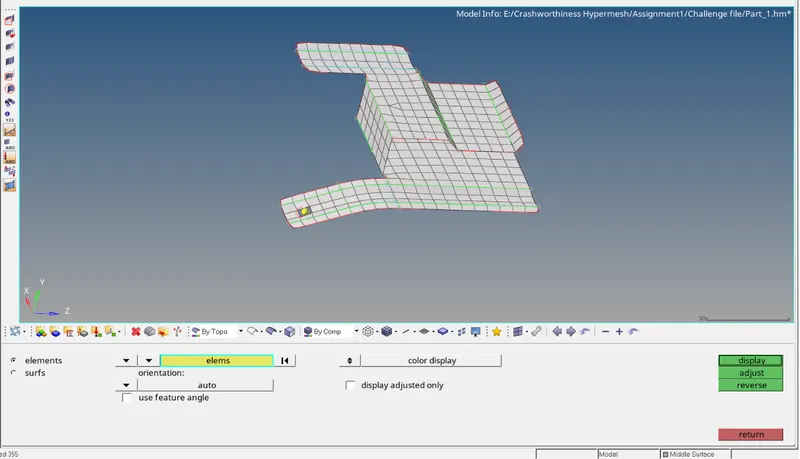
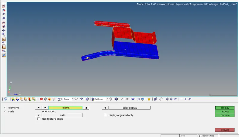
The direction of the normals are found to be okay. Now, assign thickness to the FE's by creating property. But first, let us create material. To create material, Right click on the model view > Create > Material.
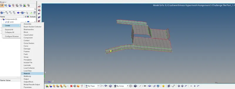
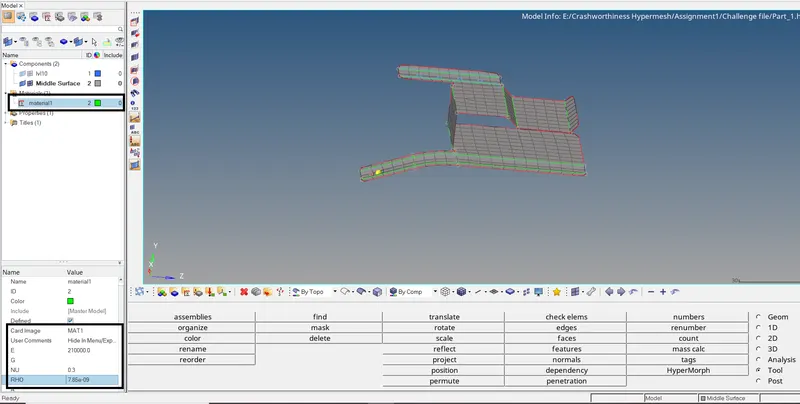
In the model view, click on the material collector and enter the valus of E, Nu And Rho.
There is already property collector present in the file. Click on it and asssign material and card image as Pshell in order to apply thickness. For thickness, enter T=0.91.
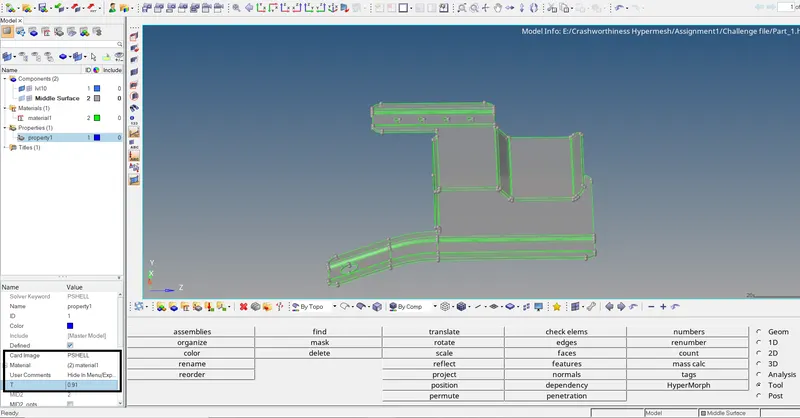
Now apply this property to the FE model. Click on the component name in the model view which contains the FE model. In the property tab, select the property we just updated.
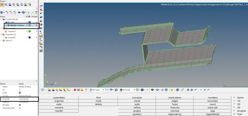
As seen above, the property is applied to the FE model. Thus, the pre-processing of the component is now completed. Save the file.
Open new file and import the second component by following same procedure discussed earlier.
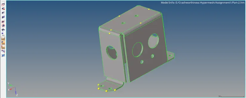
No geometry errors are found in the model. Let us proceed for geometry cleanup. Few surfaces are found, which will mess the mesh quality and min element criteria of the elements.
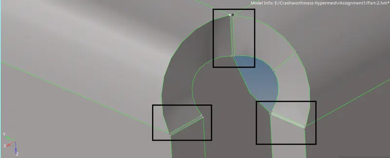
Since the distance between 2 points for these surfaces are very small, we can easily fix them by using replace point option from Quick edit panel. Press F11 > replace point.
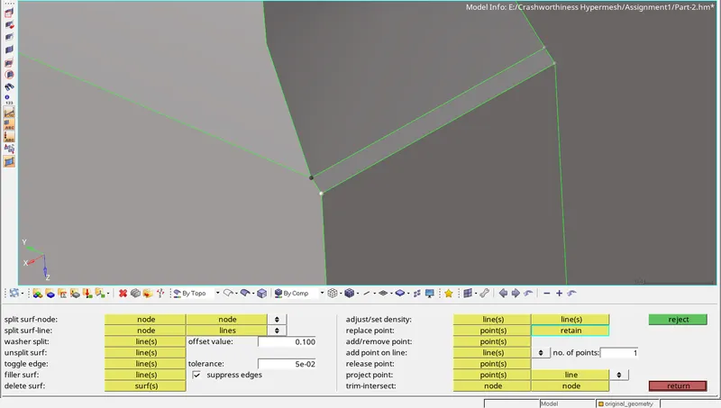
In the point selector, select the point highlighted by black color and in the retain selector, select the point highlighted in white color. Repeat similar procedure on the other side. The points will be replaced as
seen below.
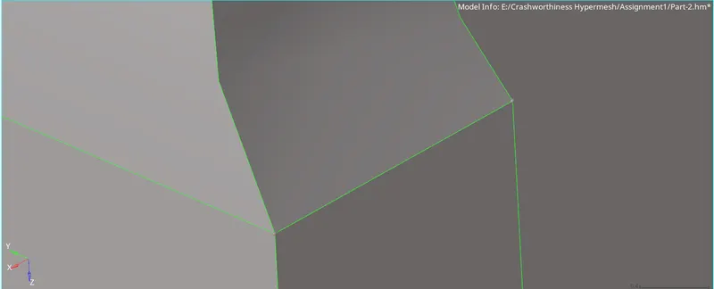
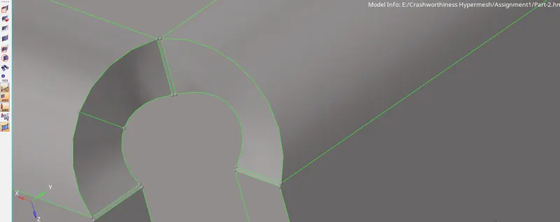
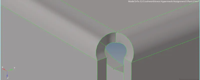
Since geometry cleanup is now completed, we can extract the midsurface. Repeat same procedure discussed in previous component to extract the mid surface and then mesh the component.
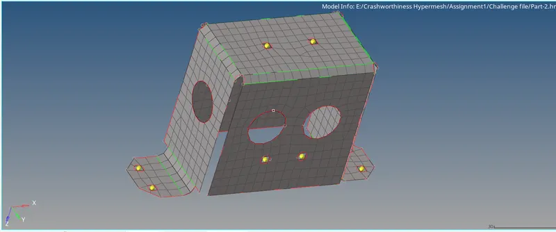
After meshing the component, check for elements failing for quality. 8 elements are found to be failing for min length near the clamping region. Since the surface and the holes are in very close proximity, the
elements will fail for for min. length criteria.
Now extract the free edges to check the connectivity of nodes / elements. Go to Tools > edges > element. Select all the elements and extract free edges. Free edges only at the outer boundary are present,
indicating all the elements are conected.
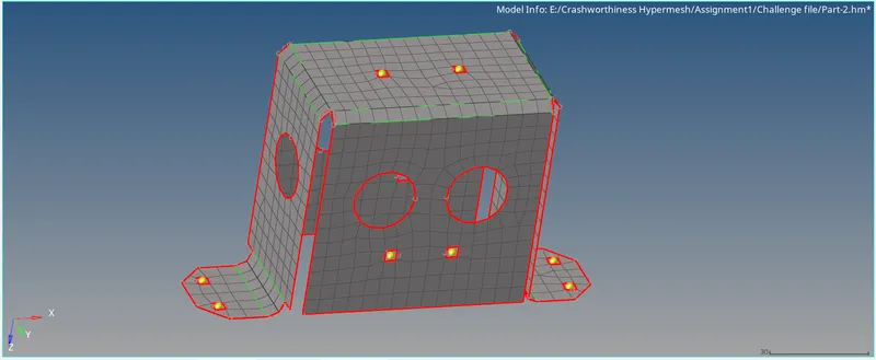
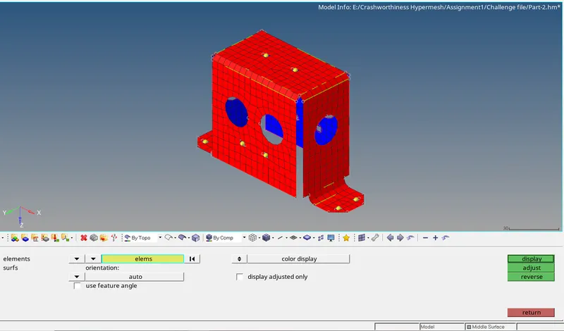
Perform the check for direction of normal. Go to Tool > Normal. Select all the elements and click on display. The direction of normal are in proper direction.
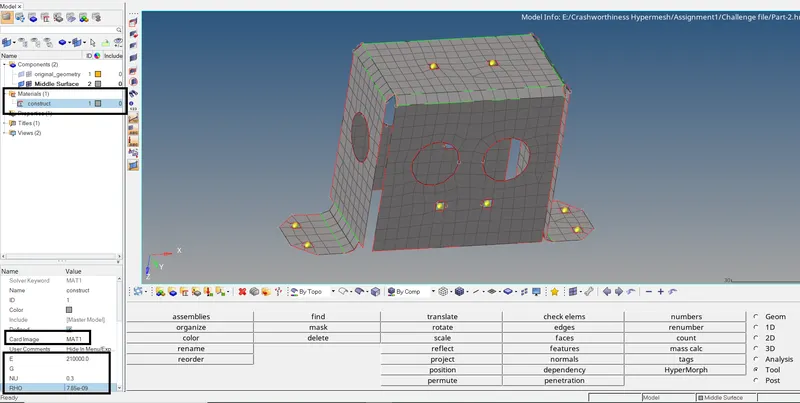
To assign thickness to the FE, we need to create property for which we need to create material first. Both these collectors are already present in the model, we need to just edit them. Click on the construct
material name under material collector. Select card image as Mat1 and enter the valus of E, Nu And Rho.
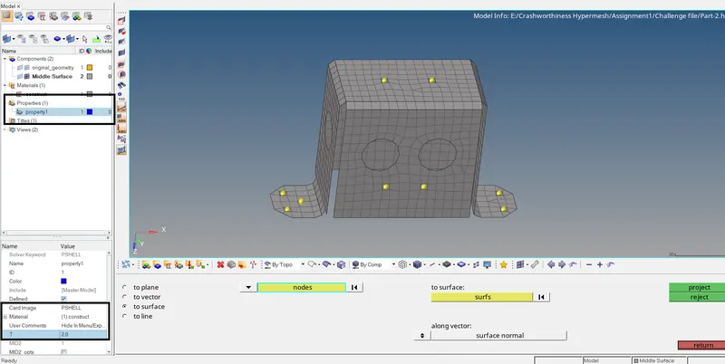
Similarly, under Properties collector, select property 1. Enter Card image as Pshell, material as construct and enter T=2.
Now assign this property to the FE. Click on the component name in the model view and select property1 in the property tab. As seenm the thickness is now applied to the FE.
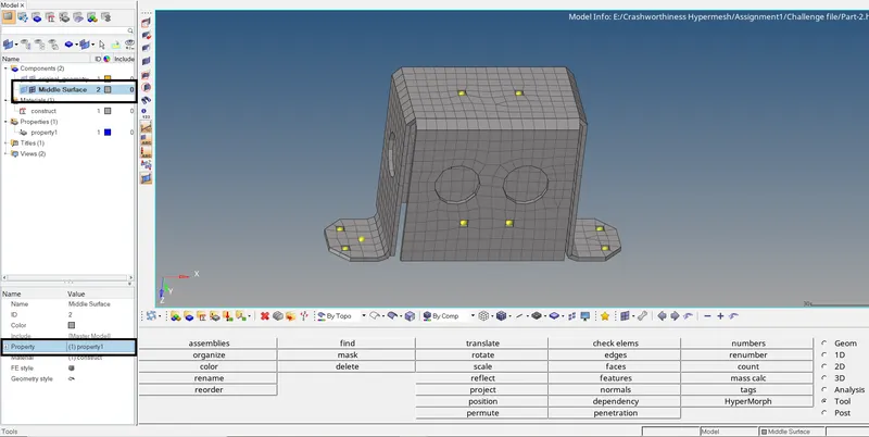
The complete pre-processing for the component is now completed. Save the file.
Now open new file and import the last component. After importing the file, the geometry is checked for geometry errors, if any present. None are found. Extract the midsurface and perform geometry cleanup
on the component. Suppress the following feature lines, as the distance between them is less than the min element size. If not supressed, the elements in this region will fail for min. element criteria.
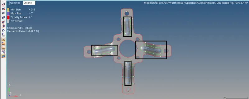
Since the component is symmetric, we can mesh only the half portion of the component and then reflect the created elements to capture the geometry. But first, let us split the component into equal portions.
go to Geom > surface edit > trim with surfs / plane > with plane. In the surf slector, select all the surface and select the circle centre as the base point. Setting the Y axis will trim the component in
perpendicular direction ,i.e in X axis. click on trim.
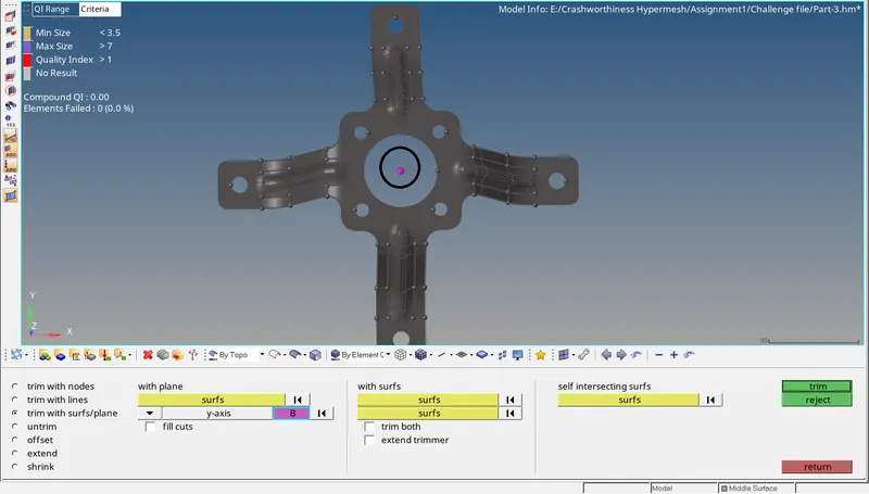
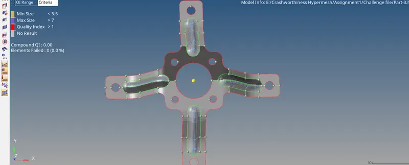
Similarly, trim the component in another direction and mesh the half portion of the component and then reflect the created elements. To reflect the elements, go to Tool > reflect. Set entity selector to elements
and select all the elements. Again click on entity selector and click on duplicate > current component. Set Y axis as the axis of reflection and select the centre of the bigger circle as the base point. Click on
reflect. The elements will be reflected.
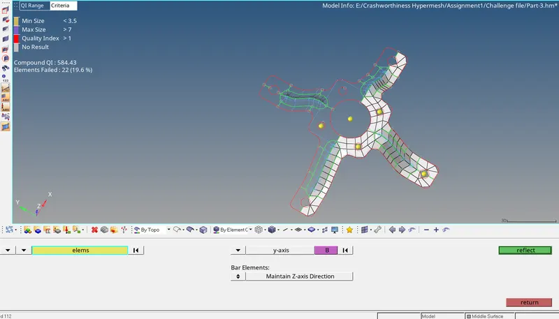
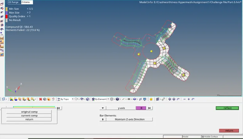
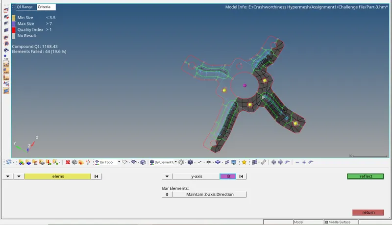
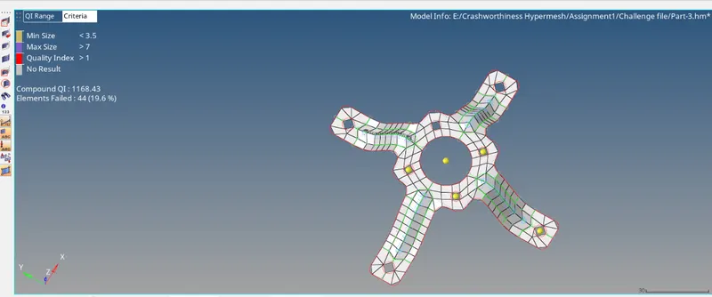
Now the entire geometry is captured. Since we have reflected the elements, the reflected elements will have free nodes about the axis of reflection. Go to Tool > edges > elements. Select all the elements
and click on preview equivalence. The free nodes will be highlighted.
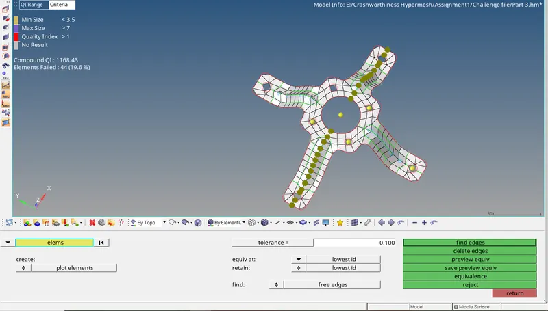
Click on equivalence. The free nodes of elements will now be connected to the nodes of the element in proximty. Remesh in the areas where mesh quality is poor or elements are failing and complete the
meshing.
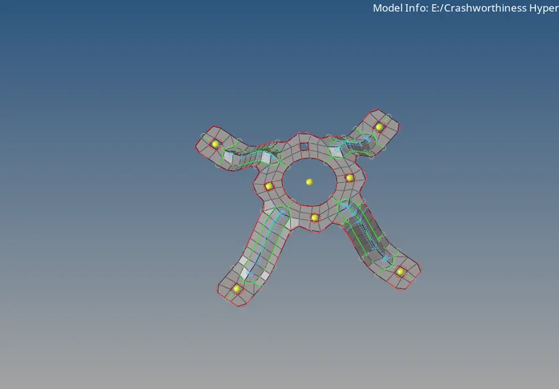
The free edges of the elements are extracted. Free edges only at the outer boundary are found as seen below.
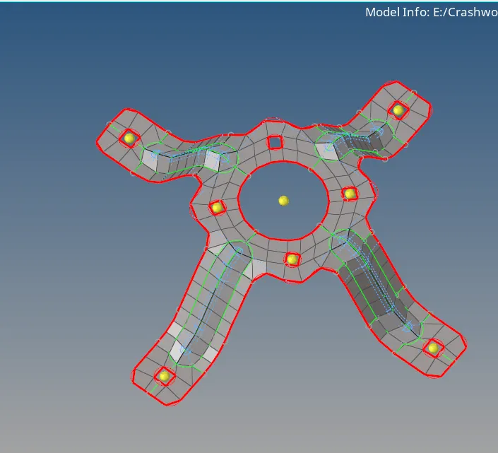
The direction of the normals are also found to be properly oriented.
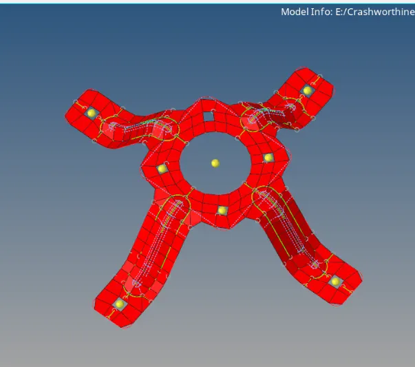
Now create material and property collector with card image Pshell with T=1.8 to define the thickness.
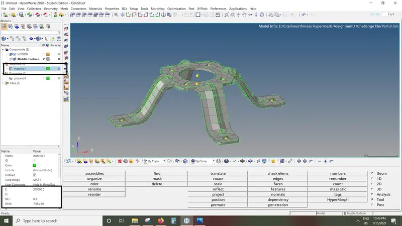
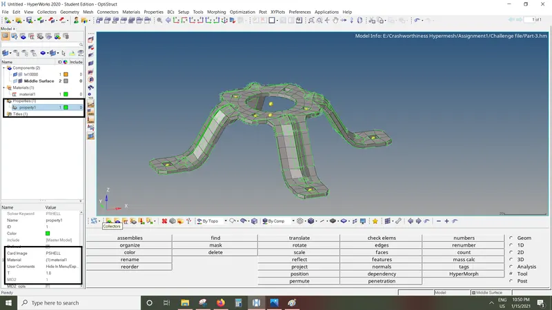
Apply the property to the FE.
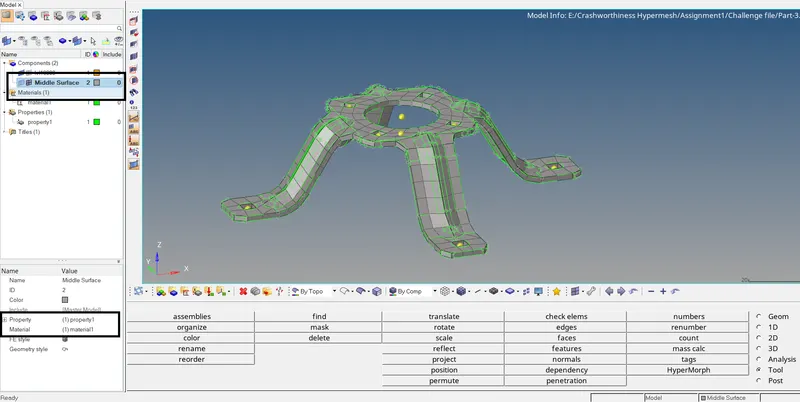
The pre-processing is now completed.
- Conclusion: We have successfully performed check for any geometric losses in the given component , geometry cleanup, extracted the mid surface and 2D meshing on the given sheet metal components
along with performing the check for connectivity of nodes of the elements and direction of the orientation of the normal of the elements after meshing. Thickness is applied to the FE created and thus the
pre-processing is completed.