Assembly of frame components by applying connectors using Hypermesh
OBJECTIVE:
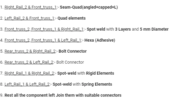
The objective of this project is to connect the frame assembly components by applying different connectors at various locations as shown below.
PROCEDURE:
1. Open the provided assembly model in Hypermesh and and change to by Topo mode.
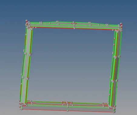
Fig: Imported Model.
2. Mesh all the components with mixed type elements of size 4mm and adjust the tria elements to maintain proper mesh flow.
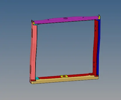
Fig: Meshed model.
3. Some of the elements are symmetric so mesh one side of the assembly and then reflect the elements to the other side.
4. Hide all the components except Right rail 2 and Front truss 1 and connect them with seam quad (angled +capped+L) type of connector. Go to 2D – connectors – Seam – select the type as (angled +capped+L) – set spacing as 4 – change to the node list by path and select the nodes – ensure quad transition is in imprint – select the components – set tolerance as 10 and weld angle as 45- Create.
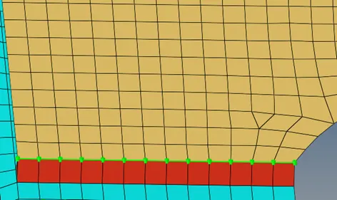
Fig: seam quad (angled +capped+L) connector.
5. The mesh flow may alter after at the connector location that need to be fixed manually.
6. To check the applied connector go to View – Browser – Hypermesh - Connectors, a separate connector tab will open.
7. For Left rail 2 and Front truss 1 apply connector using quad elements by repeating the above step but select type of connector as quad.
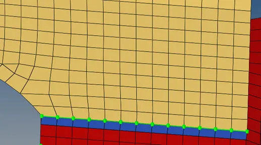
Fig: Quad elements connector.
8. For Front truss 1, 2 and Right rail 1 apply spot weld connector of 5mm diameter. Go to 2D – Connectors – spot – select the type as weld – select the nodes - change number of layers to 3 – select 3 components – set diameter as 5mm – Create.
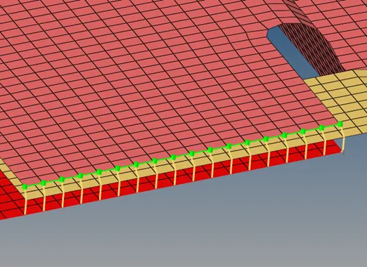
Fig: Spot weld with 3 layers.
9. Hexa adhesive connector must be applied to Front truss1, 2 and Left rail 1 as shown in fig. Go to 2D – connectors – seam – select type as hexa adhesive – set spacing, tolerance values as 4 & 10, set width as 8 and strips and coats as 1 – select the 2 components – create . Similarly repeat the same for other component.
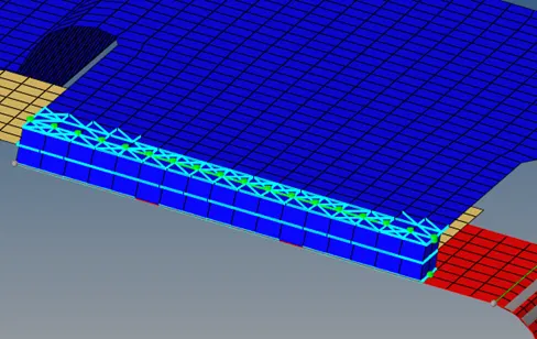
Fig: Hexa adhesive connector.
10. Switch on Rear truss 2 and Right rail 2 and select 2 nodes on Rear truss 2 component. Go to 2D – connectors - Bolt - select type as boltCBAR – since there is no holes select the create hole if none option from the same tab – select nodes, components and set tolerance as 10 – Create.
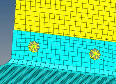
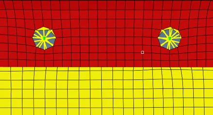
Fig: Bolt connector.
11. Repeat the above steps for Rear truss 2 and Left rail 2 bolted connection.
12. The Right rail 1 and 2 must be connected using spot weld with rigid elements. Go to 2D - connectors - spot – select type as rigid – select some of the end nodes as shown in fig. – select components and set tolerance as 10 - Create.
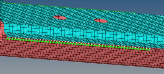
Fig: Spot weld with rigid element.
13. Similarly connect the Left rail 1 and 2 by repeating the above steps but select type as spring.
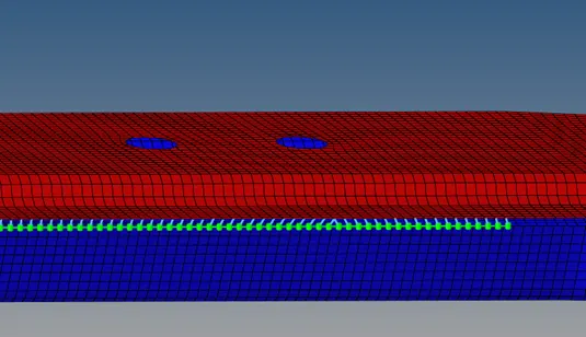
Fig: Spot weld with spring element.
14. Some components need to be connected in order to complete the assembly. The Right rail 1 and rear truss 2 were connected using bolt connector. And the Rear truss 1 and 2 were connected using spot weld with rigid components.
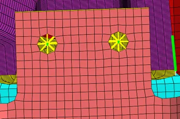
Fig: Bolt connector.
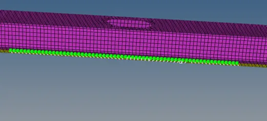
Fig: Spot weld with rigid elements.
15. The Reinf plate was connected to Front truss 2 and 1 using seam weld with seam quad (vertical+angled) type as shown in figure.
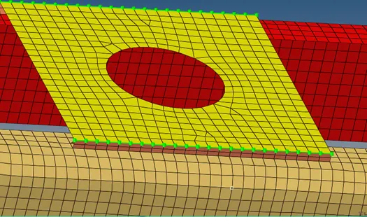
Fig: Seam (Vertical+angled) connector.
16. Front truss 2 and left rail 2 were connected using seam quad angled type as shown in figure.
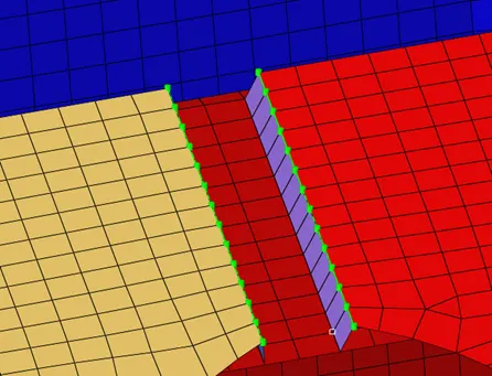
Fig: Seam quad angled connector.
17. Front truss 2 and Right rail 2 were connected using spot weld rigid elements as shown in figure.
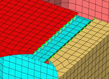
Fig: Spot weld with rigid elements.
18. Make sure that all the components were connected properly so has to obtain a single frame assembly.
RESULT:
The specified types of connectors were applied in the prescribed location and the components were connected to each other to obtain a single frame assembly.
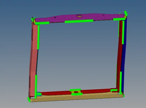
Fig: Final connected frame model.