Meshing the floor panel of an automobile
MESHING THE FLOOR PANEL OF AN AUTOMOBILE
OBJECTIVE:
The key objective of this project is to mesh the floor panel of an automobile according to the specified quality criteria by extracting the midsurface and to assign the thickness for the meshed floor panel.
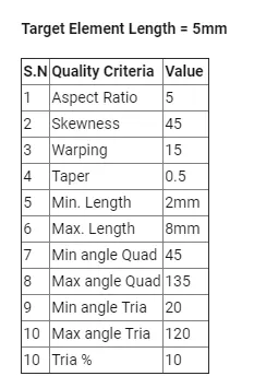
Fig: Quality criteria.
PROCEDURE:
1. Import the given floor panel model to hypermesh. Delete the solids and switch on the display fixed point. Change to by Topo mode for enhanced visualization of geometry.
2. Delete all the empty components and organize all the components in to single collector.
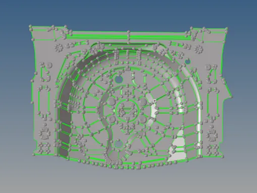
Fig: Imported floor panel model.
3. The model has some free edges and surface distortions which should be fixed using surface editing tools and quick edit tools.
4. Check the thickness of the panel at different locations using distance option. The panel has uniform thickness of 0.75mm since the panel is of sheet metal.
5. The panel has different types of contours and profiles so it is ideal to extract the mid surface manually.
6. Create a component collector for mid surface and extract the mid surface by carefully selecting the surfaces and offset them to 0.375mm by duplicating it to current component.
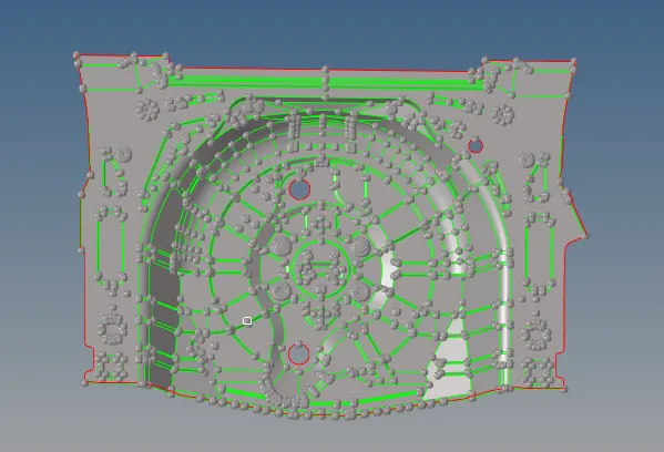
Fig: Extracted mid surface.
7. The extracted mid surface have some of the minute and intricate profiles which need to be removed and openings must be filled so has to avoid the failure of elements for quality.
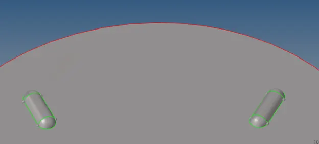
Fig: Minute profiles.
8. Toggle the unnecessary lines and avoid the sharp corners by splitting and diverting feature lines so that maximum amount of features can be captured without failing for quality.
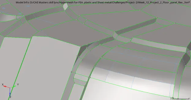
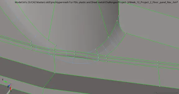
Fig: Sharp corners.
9. Divide the surfaces in to smaller proper segments so has to achieve proper mesh flow. Set the criterions in criteria file setting.
10. Mesh the surfaces starting from the center of the panel with 5mm mixed type of mesh. The tria elements are dominant in the converging profiles.
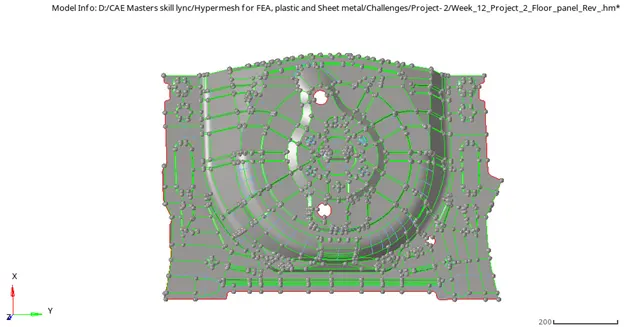
Fig: Final mid surface.
11. Most of the elements will fail for warpage that need to be fixed manually by translating the nodes.
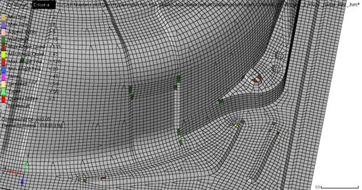
Fig: Failed elements.
12. Fix all the quality criterions for the mesh and check for free edges and normals for the mesh. Unsplit the segmentation lines.
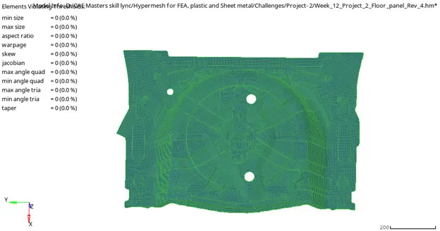

Fig: Quality check.
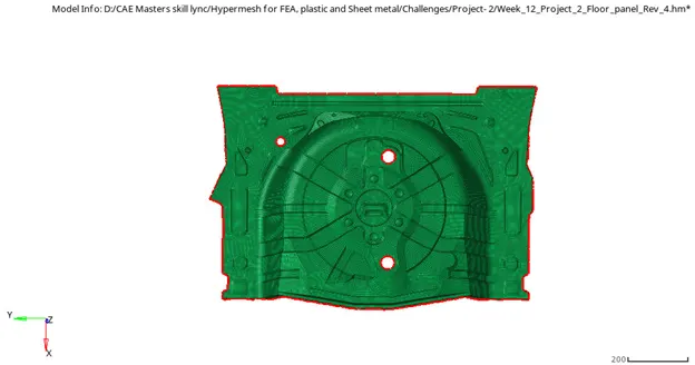
Fig: Free edge checking.
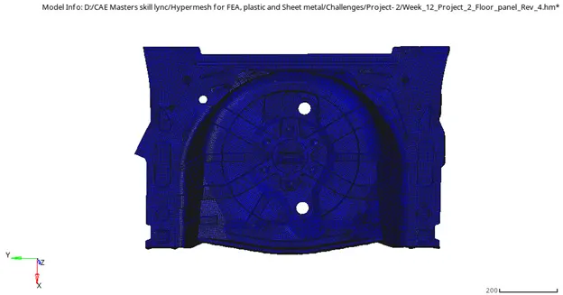
Fig: Normals Checking.
13. Assign the thickness for the mesh by creating the property card entering the thickness value in property tab.
RESULT:
The floor panel is meshed according to the given quality criteria by extracting manual mid surface and the thickness are assigned to the mesh according to the parent geometry.
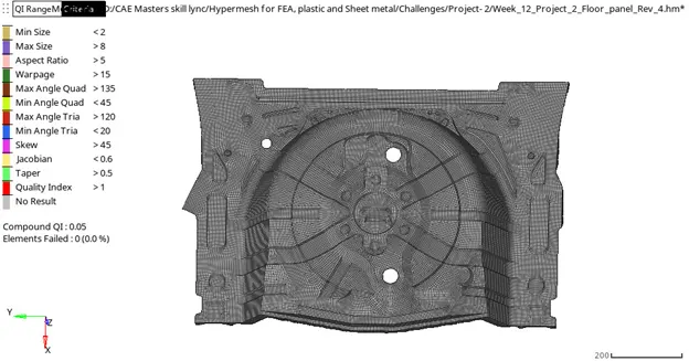
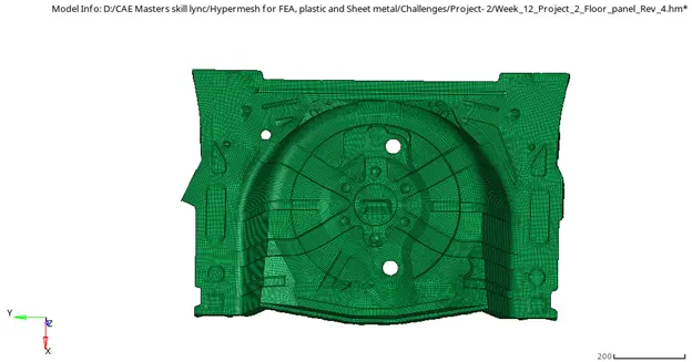
Fig: Final model.