Creation of 1D elements using Hypermesh
AIM:
To create 1D elements in the given model with respect to the specified parameters.
OBJECTIVE:
- To create Rod elements of Box cross section as per the given dimension in the specified location with only translation DOF and RBE2 link.
- To create Beam element of I cross section as per the given dimension in the specified location constraining with all DOF and RBE3 link.
- To create Bar element of Cross cross section as per the given dimension in the specified location with only X and Y DOFs with RBE3 link.
- To apply a mass of magnitude 10 on the shown location with RBE2 link.
- To create a spring element between the components in the specified location.
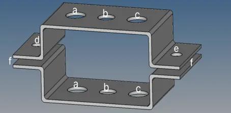
Fig: Given model.
a. Rod element, Box C/S, Dim. a - 12mm, Dim. b - 10mm, Thick. t - 0.75mm.
b. Beam element, I C/S, Dim. a - 8mm, Dim. b - 10mm, Dim. c - 8.5mm, Thick. t1 - 0.75mm, Thick. t2 - 0.6mm, Thick. t3 - 0.6mm.
c. Bar element, Cross C/S, Dim. 1 - 5mm, Dim. 2 - 1.2mm, Dim. 3 - 10mm, Dim. 4 - 1.2mm.
d & e. Mass of Magnitude 10.
PROCEDURE:
1. Import the given IGES model to Hypermesh.
Import – Import geometry – Select model – Import.
2. Delete the solids from the model which is not necessary for this case.
Delete – solids – All – Delete entity.
3. Since there are 2 components in the model extract the mid surface for the 1st
Geom – Mid surface – Change extraction option to Skin offset – Select the 1st component – Extract.
4. Rename the extracted mid surface and extract a separate mid surface for the 2nd component and rename accordingly.
Right click on mid surface in tab bar – Rename.
5. Hide the parent bodies for clarity and Perform auto cleanup for the mid surface.
Geom – Auto cleanup – Surf. – All – Auto cleanup.
6. Some of the washer split may miss or some extra split lines may appear due to auto clean up so that should be fixed manually. Provide the washer split for the holes and untrim the unnecessary edges.
Quick edit – Washer split – Set offset value – Select the edge and to trim the edges
Geom – Surface edit – Untrim – Selected trim lines from surfaces – Select the edges.
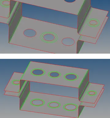
Fig: Geometry cleanup.
7. Mesh the surfaces with element size 5 and mixed type and equalize the number of nodes at the hole locations.
2D – Auto mesh – Set element size – surf displayed – Mesh. To adjust the nodes Rt. and Lt. Click on the counts near the holes.
8. Before creating the elements create material and properties for the components and elements.
Tab bar – Right click – Create – Material and similarly properties and rename accordingly.
Create properties as shown below.
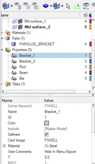
Fig: Component properties.
9. Edit the material as steel and edit property select the card image as PSHELL and assign thickness as 5 (since measured thickness of model is 5mm).
10. Assign these properties by updating the property in the mid surface.
11. Create RBE2 element with only translation DOF at location A as shown.
1D – Rigids – Create – Set to multiple nodes and calculate nodes – Select nodes – uncheck DOF – 1, 2 & 3. – Set element type as RBE2 – Create.
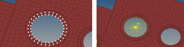
Fig: Element creation.
12. Create RBE3 element constraining all DOF at the location B as shown.
1D – Rbe3 – Create dependent – Select nodes – Check all DOF – Set element type REB3 – Create.
13. Similarly Create RBE3 element with only X and Y DOF at location C as shown.
Repeat the above step but in DOF Uncheck DOF 1, 2, 4 & 5.
14. Similarly Create RBE2 element at location D & E of the model.
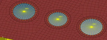
Fig: RBE2 and RBE3 elements.
15. Create Bar, Beam and Rod elements with their cross sections from Hyperbeam section.
1D – Hyperbeam – Standard section – Hyper beam – Section type – Thin walled box – Create
A separate Hyperbeam view window will open and the dimensions can be edited as per the requirement. Edit the dimension values and rename the section as Rod.
Create the Beam element of I section with the provided dimension and rename as Beam.
Rt. Click on the Hyperbeam entity tab – Create – Standard section - Hyperbeam - I section – edit the dimensions.
To create Bar element of cross cross section repeat the same procedure but instead of Hyperbeam select Optistruct – Cross – edit the dimensions – Rename as Bar. Click the Model view to get back to the working window.
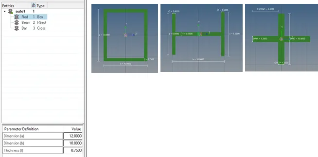
Fig: Rod, Beam and Bar element in Hyperbeam.
16. Assign the properties for Rod, Beam and Bar elements and update their cross sections in properties.
Click on Rod in the property – Set card image to PROD – Select material as steel – Beam section as Rod. Similarly for Beam – Set card: PBEAM – Material: steel – Beam section: Beam and for Bar – Card image: PBAR – Material: Steel – Beam section: PBAR.
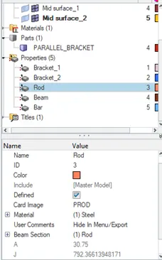
Fig: Element property.
17. Create a Rod element between the components at location A as shown.
1D – Rods – Create – Select property as Rod – Element type CROD – Then select the intersected center nodes of RBE2 links of both components.
18. Create a Beam element between the components at location B.
1D – Bars – Select property as Beam – element type: CBEAM – Select the center nodes of REB3 link and for orientation select normal plane nodes.
19. Create a Bar element at location C by connecting 2 components.
1D - Bars – Select property as Bar – element type: CBAR – Select the center nodes of REB3 link and select normal plane nodes for orientation.
20. Add a mass of magnitude 10 at D & E location of RBE 2 link.
1D – Masses – Select the center node of link – set element type as CMASS – Create.
21.Create a spring element connecting 2 components at location F.
1D – Springs – Select element type as CELAS1 – Select Nodes.
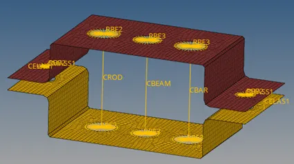
Fig: Rod, Beam, Bar and Spring elements.
22. To view the representation of the 1D elements click to 1D detailed element representation from the tool bar.
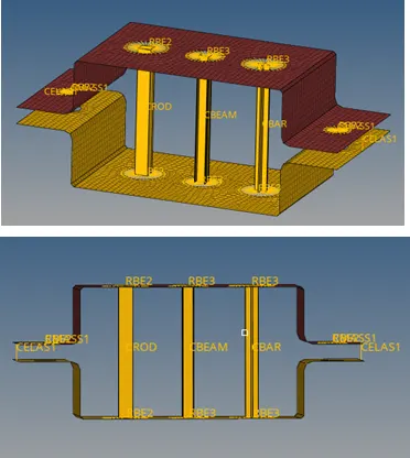
Fig: Final model with elements.
RESULT:
For the given model the Rod, Beam, Bar and spring (1D) elements were created with RBE2 and RBE3 elements (Links) at the given locations according to the specified properties and parameters. The masses were added according to the given criterions.