3D Tetra meshing of Housing and Chassis assembly of an automobile
MESHING OF HOUSING COMPONENTS.
OBJECTIVE:
The objective aims to mesh with 3D tetra elements by creating 2D shell elements for the provided housing components by maintaining the below mentioned quality criteria.
Min. Element size – 2mm, Target Element size – 5mm, Max. Element size – 7mm (For 2D shell elements)
Tet Collapse – 0.15. (For 3D Tetra elements)
PROCEDURE:
1. Import the provided model to Hypermesh and check for solids if found delete from the model. Change the view option to By topo and switch on the display fixed point.
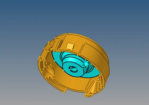
Fig: Imported Housing Model.
2. Since there are 2 components make the working component as current component and check for the surface openings.
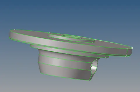
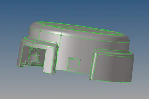
Fig: Surface Geometry.
3. Since the target element length is 5mm the lines which has below 5mm of gaps must be toggled and the surface radius of below 2mm has to be removed using defeature option. The sharp corners must be avoided by toggling the lines.
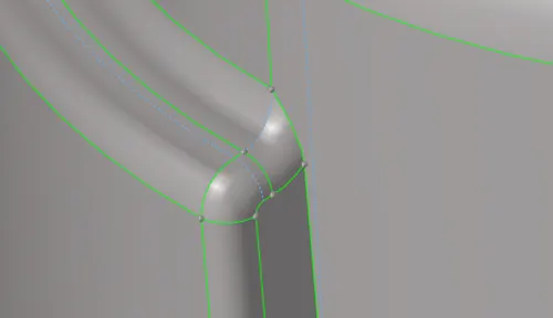
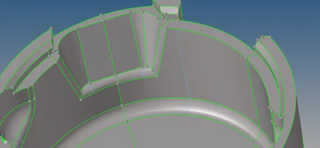
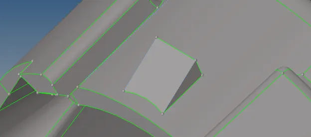
Fig: Geometry cleanup.
4. Mesh the surfaces with tria elements of 5mm size and check for failed elements from check elements panel (for Max. and Min. size) if found need to be fixed by remeshing or by translating nodes manually.
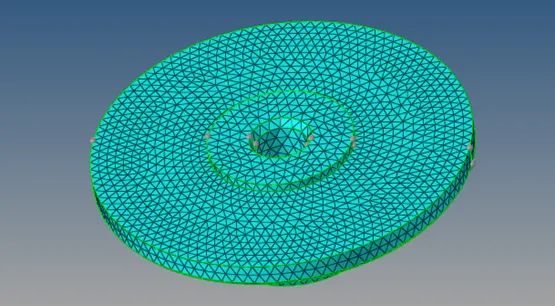
Fig: 2D Meshing.
5. Once all the 2D elements clears the quality criteria the 3D tetra elements were generated using 2D tria elements. Go to 3D – Tetramesh – Tetramesh – Select elements – Displayed – Mesh. To check the mesh formations mask some of the elements.
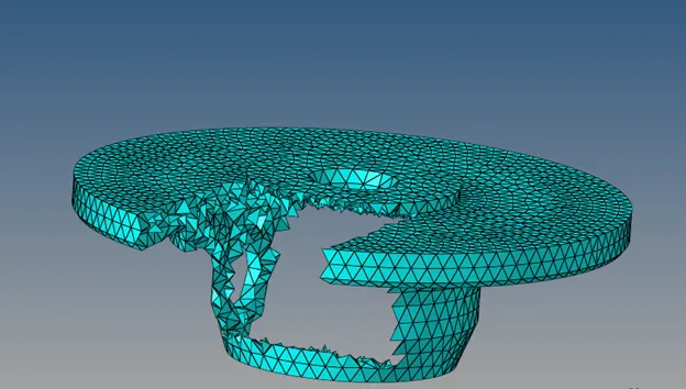
Fig: 3D Tetra meshing.
6. Check for tet collapse Go to Tools – Elements check – switch to 3D – Tet collapse enter value as 0.15 check if found the mesh must be remeshed again.
7. Go to 3D - Tetramesh – set tetra remesh parameter like Max., Min. and Tet collapse value. Switch to Tetra remesh – select displayed elements – remesh.
8. Again check for tet collapse usually all the elements will clear the criteria after remeshing if still present then that need to be fixed manually either by translating the nodes or by replacing them. While fixing manually mask the failed components and reverse them.
9. Similary repeat all the above said steps for other component to complete the meshing.
RESULT:
The given housing components were meshed with 2D tria elements according to the given quality criteria and then the components were meshed with 3D tetra elements by utilizing 2D shell elements and maintained the quality provided for 3d tetra elements.
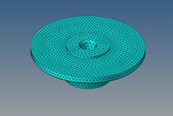
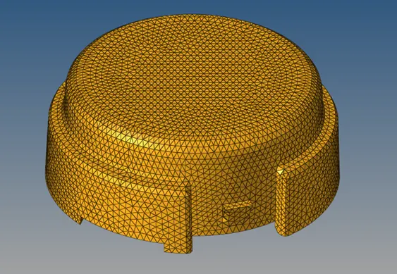
Fig: Meshed final Components.
MESHING OF CHASSIS ASSEMLY.
OBJECTIVE:
The objective is to mesh the given chassis components with 6mm sized tetra elements and to maintain the tet collapse value above 0.15 so has to maintain the quality.
PROCEDURE:
1. Import the provided model to Hypermesh. Change the view option to By topo and switch on the display fixed point. Since the model is symmetric it’s sufficient to mesh only one side. 2 geometries were present in single collector so one component need to be moved to other collector.
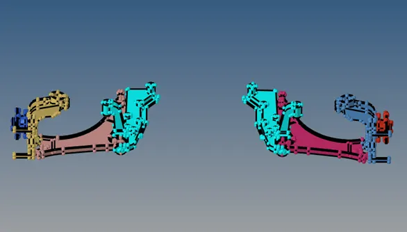
Fig: Imported Model.
2. Create a component and make as current and go to Tools – organize – select one side of the component – surfaces and solids – set destination component – move.
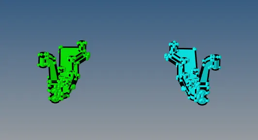
Fig: Organized components.
3. The model consists of 4 symmetrical parts where the hub part must be meshed with 2D to 3D method and remaining parts can be meshed directly using solids.
4. Make current component as hub component and delete the solids and defeature the fillets and holes as shown in figure.
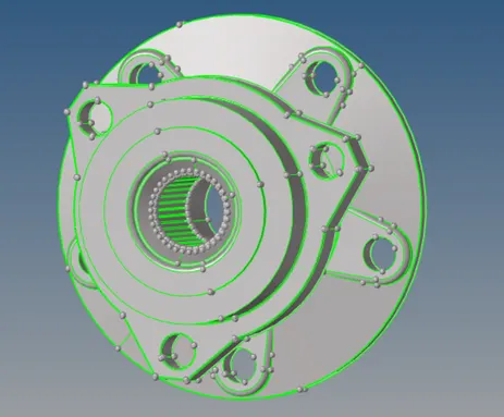
Fig: Hub Component.
5. The gear teeth nodes must be joined in order to remove them and mask the outer surfaces to obtain better visualization.
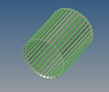
Fig: Gear teeth.
6. The deleted teeth surface must be filled with plain cylinder using ruled option as shown in figure.
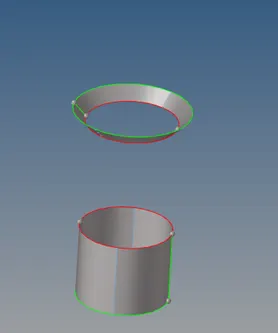
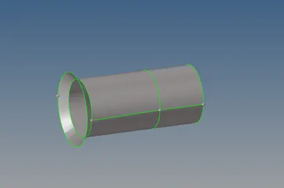
Fig: Filled surface.
7. Toggle the required lines which falls below the minimum element length I;e 3mm.
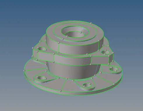
Fig: Cleaned surface.
8. Follow the above mentioned steps for 2D to 3D meshing but maintain target element length as 6mm and clear the tet collapse.
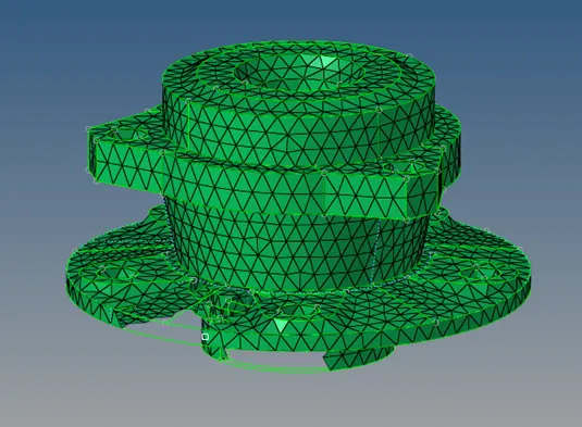
Fig: 2D meshing.
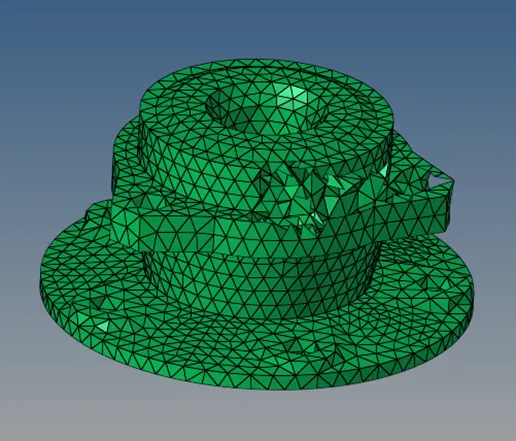
Fig: 3D Meshing.
9. The other components consists solids that can be directly meshed using volume tetra. Go to 3D – Tetramesh – set tetra remesh parameters – volume Tetra – select volumes – set element size as 6mm – mesh.
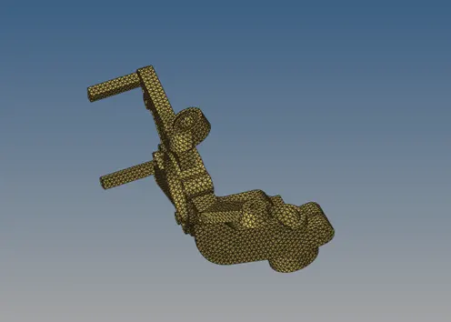
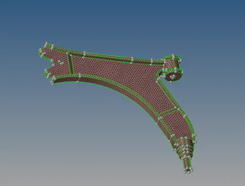
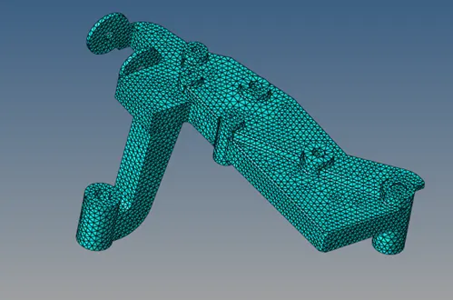
Fig: Volume meshing.
10. If volume tetra is showing error try the same for the partial side components and later that can be reflected
11. Check for tet collapse if found remesh and follow the above said procedures.
12. To create a base point for reflection go to Geom – Nodes – Arc center – select the lines. Similarly repeat same procedure for other side.
13. Go to distance - 2 nodes – select created nodes – click nodes between. A center node will be created which can be used as base point.
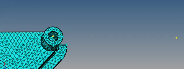
Fig: Base node creation.
14. Since the components are symmetric delete one side of the model in order to maintain the number of nodes with in the limit.
RESULT:
The given chassis components were meshed with tetra elements by maintaining the given quality parameters.
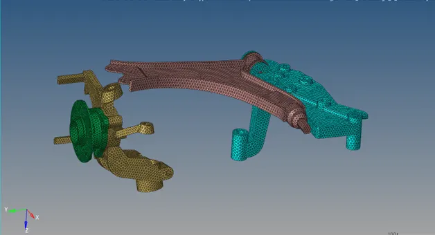
Fig: Meshed final assembly.
MESHING OF CRANK HOUSING.
OBJECTIVE:
The objective aims to mesh the given geometry with 6mm tetra mesh by maintain the tet collapse value above 0.15.
PROCEDURE:
1. Import the model to the hyper mesh and switch on the display fixed point and change to by topo mode.
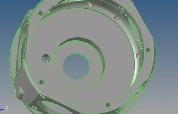
Fig: Imported model.
2. The geometry has some open surfaces that need to be toggled and toggle the other required lines.
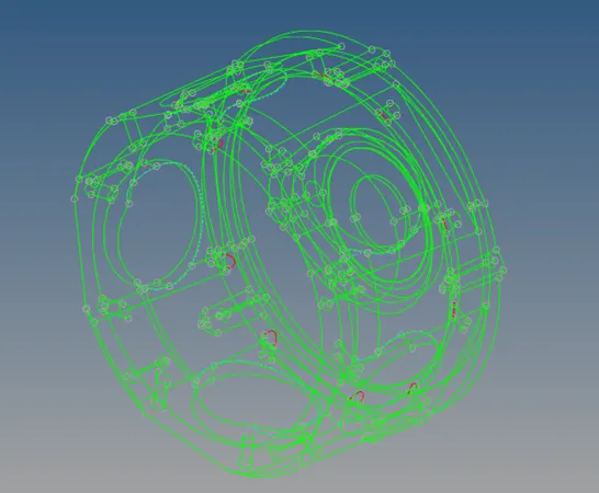
Fig: Surface openings checking.
3. Repeat the above mentioned steps for volume tetra option but instead of solids select surfaces and mesh.
4. Remesh the same in order to fix the quality criterions if still errors found manually fix the nodes.
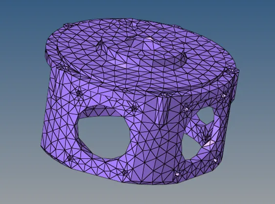
Fig: Meshed final model.
RESULT:
The given crank housing is meshed according to the given parameters by maintaining its quality criterions.