Meshing the side door trim of an automobile in Hyper Mesh
MESHING OF SIDE DOOR TRIM
OBJECTIVE:
The objective of this project is
- To mesh the side door according to the given quality criteria by extracting midsurface and performing topology cleanup for the same.
- To assign the thickness for the meshed components as per the model.
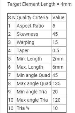
Fig: Quality criteria.
INTRODUCTION:
When the geometry has smaller thickness value when compared to its span length its ideal to mesh the components with 2D elements by extracting the mid surface and then assigning the properties like thickness and material for the mesh so has to achieve the original properties of the geometry. Most of the automobile panels (both sheet metal and plastic components) has large surface span when compared to its thickness hence this method is very much preferred in industry. This method has 3 major steps,
1. Topology cleanup.
It is necessary to perform topology/geometry cleanup for the components in order to eliminate the geometrical errors, critical surfaces and to enhance the mesh quality and flow. The process includes defeaturing/removing of surface and edge fillets, pinholes, filling of surface openings and fixing free edges. Most of the automotive plastic components are of complex shapes that have to be cleaned before further operations.
2. Mid surface extraction.
Mid surface is the exact replica of the geometry in a 2D surface form where the surfaces were generated or extracted according to the parent geometry. The midsurface is meshed and properties and thickness will be assigned depending on the parent geometry. If the geometry has varying thickness then the mid surface must be extracted manually. Most of the automotive plastic component will have varying thickness so multiple mid surfaces must be extracted according to the parent geometry.
Some of the advantages of midsurface and 2D meshing are as follows.
- Without much difficulty accurate results can be achieved.
- Reduces the meshing time by reducing the number of elements (3D meshing requires much more time)
- Reduces the processing time and computation time by increasing the simulation speed.
- Any revisions or mesh modifications can be done easily.
3. 2D meshing.
A 2D solid is a two-dimensional element that represents a slice of a solid. 2D elements either can be 4 node quad element or 3 node tria element. The automotive plastic components are analyzed for crash and impact so combination of quad and tria elements can be used for meshing. The extracted midsurface is meshed with 2D elements which are simplest representation of 3D elements in 2 dimensional the third direction will comes in to picture when the thickenss is assigned to the 2D elements. Thus 2D elements reduces computational time by simulating the analysis at higher speeds.
PROCEDURE:
1. Import the given side door model to hypermesh. Delete the solids and switch on the display fixed point. Change to by Topo mode for enhanced visualization of geometry.
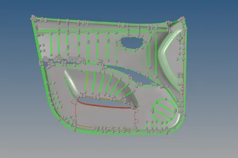
Fig: Imported model.
2. Since the door has some complex profiles it is ideal to divide the model in to smaller segments as shown in figure. Go to – Geometry – Surface edit – Trim with lines - select surface - Drag line.
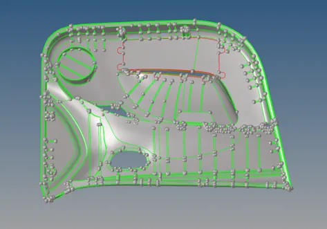
Fig: Divided model.
3. Arrange the segmented surfaces in to different collectors for convenience and isolate the required surface. Tools - Organize – Select surface and components –move.
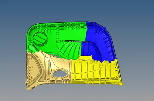
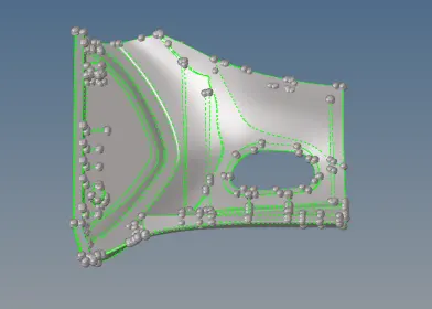
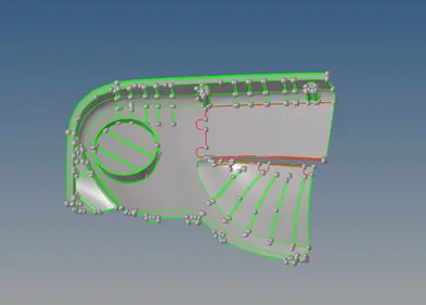
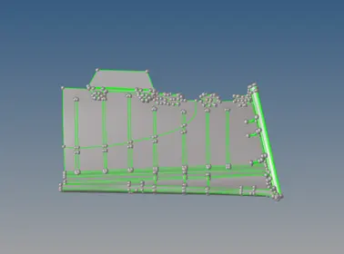
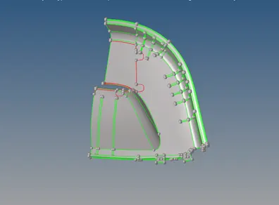
Fig: Organized surface parts.
4. Defeature the fillets on the ribs and fillets on the surfaces for better mesh flow and quality and fix the openings and surface errors in the parent geometry.
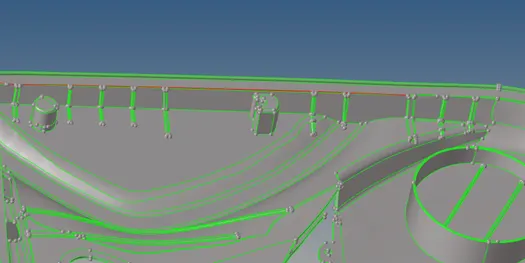
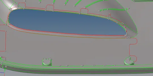
Fig: Surface Errors.
5. Measure the thickness of the surfaces, since the model has varying thickness and extract the midsurface manually by offsetting the surfaces. Go to – Geometry – surface edit- Offset – select surface- Duplicate in current comp. – set the offset value – offset. Some of the surface has opening issues so offset the outer surface to resolve the problems.
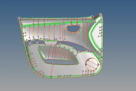
Fig: Joined midsurface.
6. Similarly offset the rib surface and extend the surface using extend option from surface edit panel. Geom - Surface edit- extend – select line and target surface- extend. Some of the ribs have varying thickness then use mid line option from lines and trim the surface with mid liens and connect both the lines using ruled option.
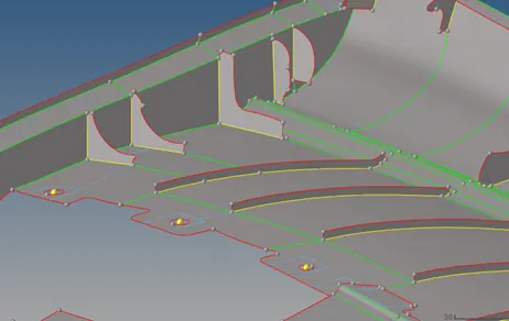
Fig: Midsurface for ribs.
7. Finally join the segmented surfaces for meshing and toggle the line which falls below the minimum length and uneven.
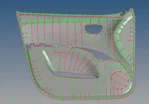
Fig: Final midsurface.
8. Set the criterions in criteria file setting and mesh the mid surface with mixed type and size of 4mm and divide the surface according to the requirement. Fix the quality of mesh according to the specification. Check for free edges and normals.
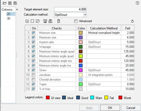
Fig: Criteria file setting.
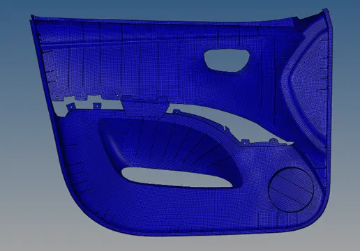
Fig: Meshed model.
9. The meshed elements then organized in to different collectors according to their thickness so has to assign the thickness for the elements. Create components and move the elements accordingly.
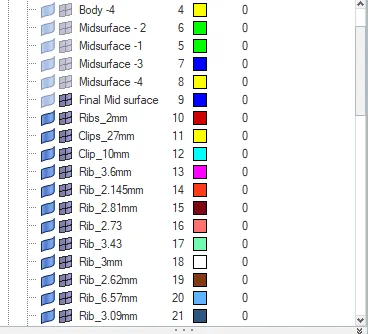
Fig: Creating components.
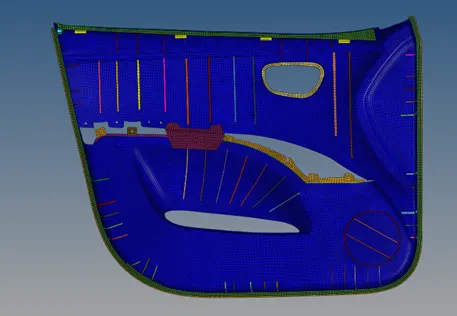
Fig: Organizing elements.
10. Create the properties and enter the thickness values according to the measured value and assign the thickness for the components.
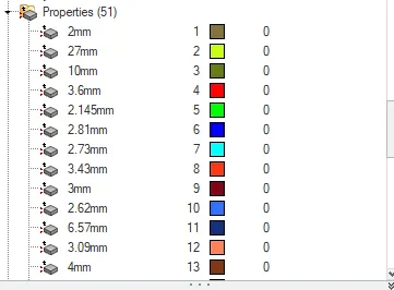
Fig: Creating properties.
RESULT:
The given automotive plastic side door panel is meshed according to the prescribed quality criteria by generating manual midsurface and the thickenss were assigned to the elements according to the side door parent geometry.
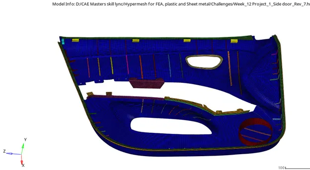
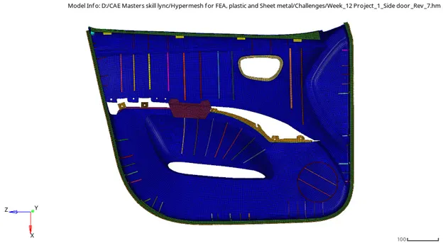
Fig: Final model.