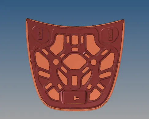
Meshing and quality check of Hood components.
OBJECTIVE:
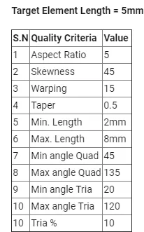
The key objective of this project is to extract the separate mid surfaces, perform topology cleanup and mesh the given hood components by maintaining the below specified quality criterions for the mesh.
PROCEDURE:
MID SURFACE EXTRACTION
1. Import the provided stp model to Hypermesh and delete the solids from the model. Change the view option to By topo and switch on the display fixed points to get better visualization.
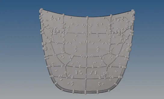
Fig: Imported Model.
2. Since the hood components are of sheet metal directly we can extract the mid surfaces by omitting the topology cleanup for parent components.
3. We need to extract separate mid surface for each and individual components. While extracting the mid surfaces make sure that the respective parent component is selected as current component and continue the same procedure for all other components. While extracting select extraction option as skin-offset and rename the mid surfaces according to the parent.
Ex: If we need to extract the mid surface for the Latch part then the Latch parent component should be change to current component.
4. Once all the mid surfaces were extracted hide all the parent geometry. There are 5 mid surfaces I;e 1. Latch, Hinge 1, Hinge2, Outer panel, Inner panel. Perform topology cleanup for the mid surfaces starting from Latch part.
TOPOLOGY CLEANUP
Before performing topology cleanup select the respective components mid surface as current component and hide rest of the mid surfaces other than the current mid surface.
1. Starting with latch mid surface, replace the points as shown below and toggle the necessary lines so has to achieve better surface geometry. Check for edge fillets below 5mm from Defeature option and delete them and ensure that the surfaces are properly filled.
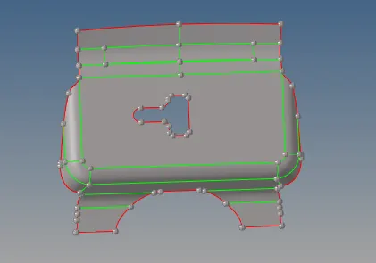
Fig: Extracted Latch Mid surface.
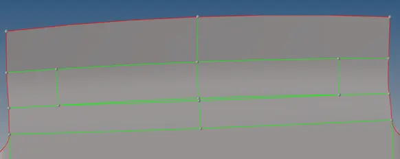
Fig: Deflected lines.
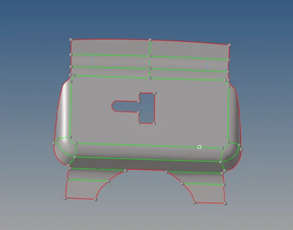
Fig: Cleaned Latch Mid surface.
2. Change to Hinge part by following the above mentioned step to start topology clean up for the Hinge mid surface. Since there are 2 symmetrically Hinge mid surfaces perform topology cleanup for only one mid surface and leave the other mid surface. Toggle the lines which have below 2mm of gaps as shown in figure and provide a washer split of 5mm for the hole so has to get better mesh flow around the hole.
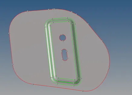
Fig: Extracted Hinge 2 Mid surface.
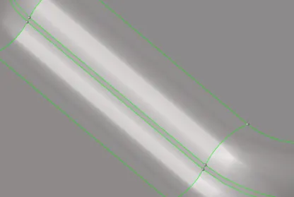
Fig: Lines which has gap of below 2mm.
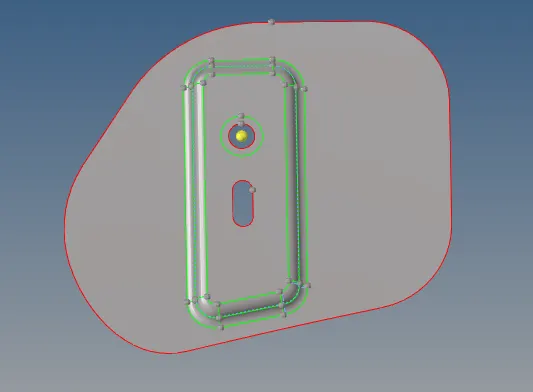
Fig: Cleaned Hinge 2 Mid surface.
3. Shift to the outer panel mid surface to perform geometry cleanup for the same. Since the outer panel is a symmetric we can delete the one side of the surface from the symmetrical axis line (Centre line). The topology cleanup is performed for the one side of the component as shown in figure.
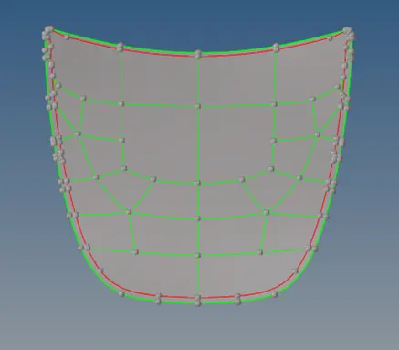
Fig: Extracted Outer panel mid surface.
4. Toggle the unnecessary lines and replace the points in the hem surface to obtain single radius line. Split the surface in to smaller regular surfaces so has to obtain better mesh flow. Toggle the surface lines and make the center line as dividing line to avoid failure of elements.
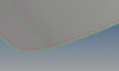
Fig: Irregular lines on Hem surface.
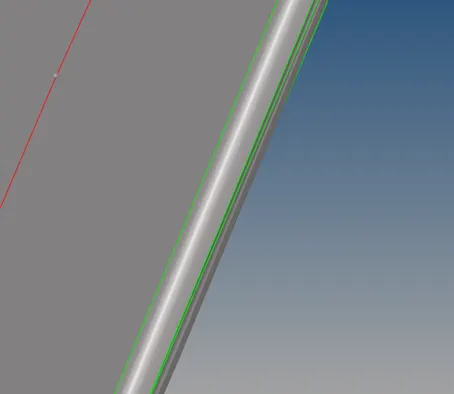
Fig: Hem surface of outer panel mid surface.
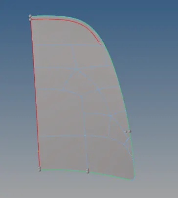
Fig: Cleaned outer panel mid surface.
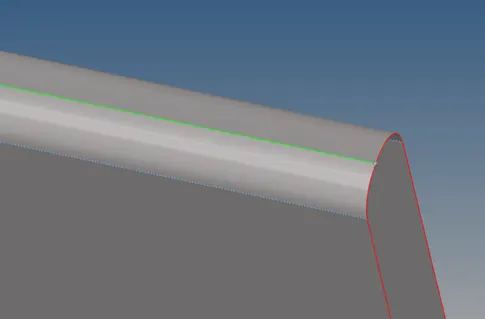
Fig: Cleaned hem surface of outer panel.
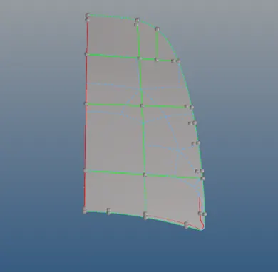
Fig: Final mid surface of the outer panel.
5. Switch to the inner panel mid surface. Most of the inner panel surfaces are symmetric in nature so delete the one side of the surfaces which are symmetrical and keep the other portion as it is. While deleting the surfaces ensure that the center lines are connected properly otherwise the entire surface will be deleted.
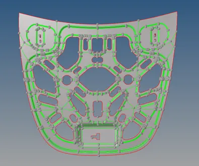
Fig: Extracted Inner panel mid surface.
6. Toggle the unnecessary lines and there should not be any lines whose distance is below or nearly equal to 2mm. At the intricate regions and fillet junctions divide the surface in to smaller portions and avoid the sharp cornering at the fillet regions. Remove surface fillets which are below 5mm using defeature option.
7. Toggle the mismatched lines and connect the nodes such that there should be continuous line throughout the surface as shown in figure. Split the surfaces in to smaller regular surfaces as shown in figure in order obtain good mesh flow.
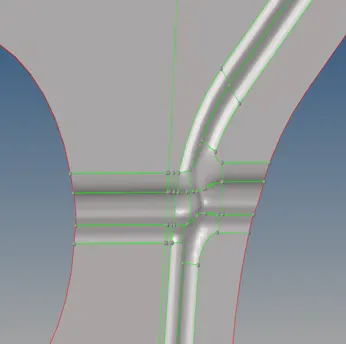
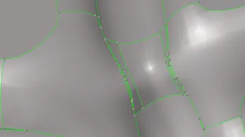
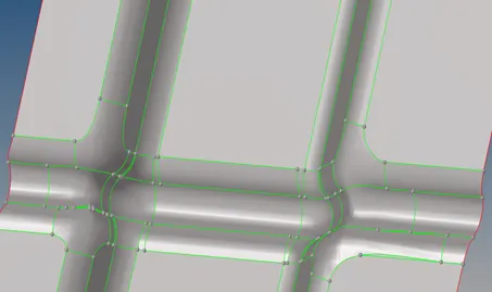
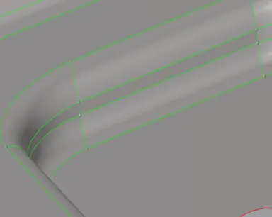
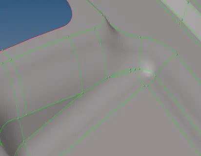
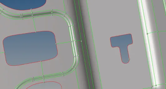
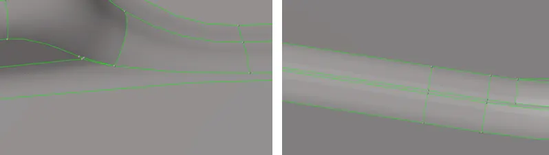
Fig: Inner panel mid surface defects.
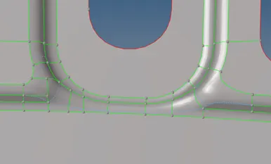
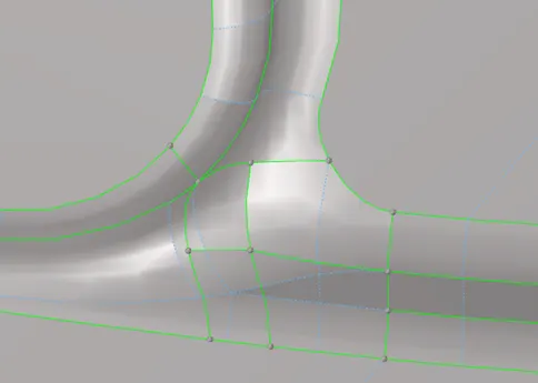
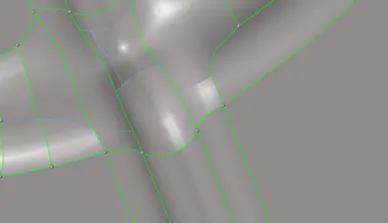
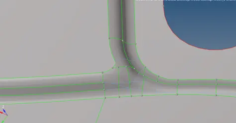
Fig: Cleaned mid surface of inner panel.
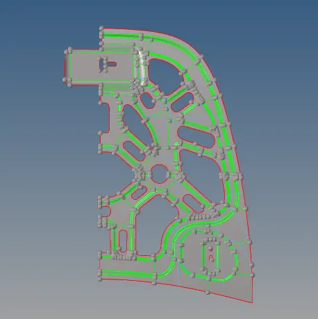
Fig: Final mid surface of Inner panel.
MESHING
Before starting meshing set the criterions provided for the quality of the mesh. In order to set the criterions go to Preferences, Criteria file setting, enter the values provided accordingly and apply, ok.
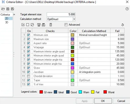
Fig: Criteria file setting.
While meshing select the respective mid surface as current component and hide the rest of the mid surfaces.
1. Starting with the latch part before starting the mesh set the mesh topology revision as Advanced re-mesh in order to do that Go to Preferences, Meshing options, Mesh, Topology revision.
2. To mesh the surfaces go to 2D, Auto mesh, set element size 5, mesh type as mixed and check the align and size from the flow tab and select the surface and mesh, adjust the number of nodes depending on the mesh flow and try to maintain even number of nodes. Mesh the component surface by surface rather than single mesh.
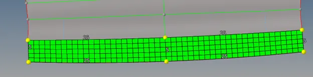
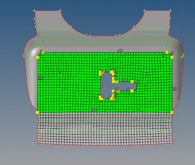
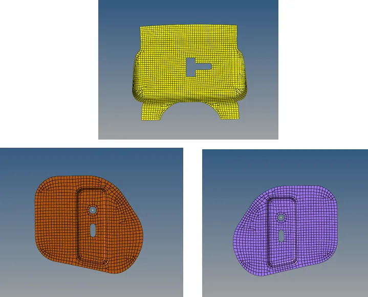
Fig: Meshing of latch.
3. To avoid the tria element concentration repeat the above step instead of surface change to elements, re-mesh the elements by selecting them.
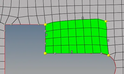
Fig: Remeshing.
4. The color of the mesh and surface will be same it will be difficult instead of manually changing the colors go to Tools, color, select Auto color, and switch the component to wire frame for better visualization.
5. To further edit the mesh and check the quality go to 2D, quality index it will shows the failed elements some of them can be fixed using clean up tools like swap edge, Drag tria, place node, split quad, combine tria. Etc. depending on the requirement.
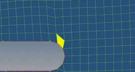
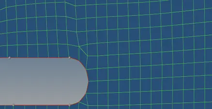
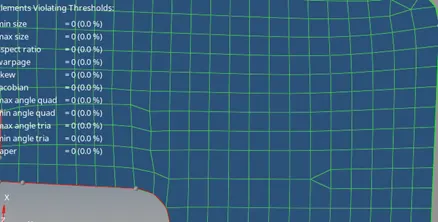
Fig: Mesh clean up.
6. The tria elements can be moved by replacing the nodes. Go to 2D, replace select the 2 base nodes of tria and check at midpoint and replace.
7. While arranging the mesh avoid deviation of elements from feature line, opposite tria’s, back to back tria’s, tria’s connected to each other, rotational quads and tria’s at the edges and feature lines.
8. In the latch part the additional split lines were added as shown in figure in order to avoid tria element at corners. While splitting the surface after meshing change the topology revision to keep mesh, after splitting change to Advanced re-mesh.
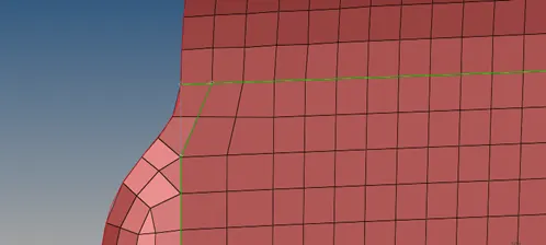
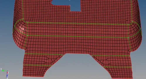
Fig: Splitting of surfaces to avoid corner tria element.
9. To enhance better mesh flow lines smooth the elements. Go to 2D, smooth, select elements, set the iterations to 10 and smooth.
10. To correct the alignment of nodes with lines we can project the elemental nodes to the particular line. Go to Tools, Project, To lines, select nodes and lines and project.
11. Once all the qualities are cleared check for the elemental free edges to ensure proper connectivity. Go to Tools, Edges, select displayed elements, set tolerance as 1.2, find edges if there is any gap was found then that should be fixed using equivalence or by replacing nodes.
12. To get better visualization of the edges go to visualization option, select the transparency icon, select the component that need to be viewed, to get back to normal view select solid icon and select the component again.
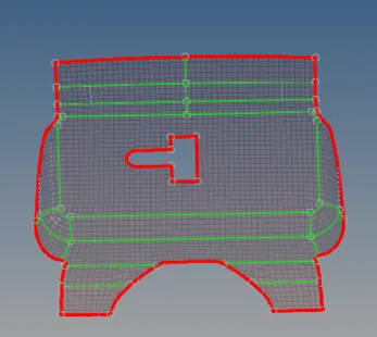
Fig: Free edge checking.
13. Finally check for the Normals where all the elements are faced in the same direction. Go to Tools, Normals, select the displayed elements and change to color display, Display. The elements should have the same colors on the surface.
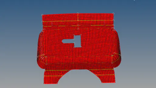
Fig: Normal checking.
14. Switch to the cleaned Hinge part by repeating the above mentioned steps. Select the inner surface and mesh. To avoid the tria elements repeat the above mentioned tools and steps.
15. The converging shape of the hinge creates feature tria elements so keep 2 trai elements on the either side of it as shown in figure in order to arrange the mesh uniformly.
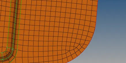
Fig: Tria arrangement.
16. Check for Normals and free edges as mentioned in the above step. The meshed hinge should be reflected to the other side so has to obtain mesh for the other hinge. To reflect a base point must be created at the center of 2 Hinges. Go to Geom, nodes, Arc center, change to lines select the center of the hole of hinge 1 and hinge 2. Go to Geom, Distance, select created nodes, click Nodes between.
17. Make the un worked hinge as current component. And delete the un worked hinge mid surface. To reflect the surface set the view to particular axis and go to Tools, Reflect, Select surface, duplicate, current component, and select axis with respect to view axis and select base point as created mid node. And repeat the same procedure for the mesh reflection.
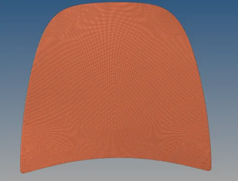
18. Mesh the outer panel by switching it to the outer panel mid surface. Repeat the above mentioned steps in order maintain the quality, mesh flow and tria management.
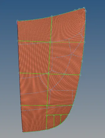
Fig: Meshed Outer panel.
19. Once all the parameters were satisfied change the mesh topology to keep mesh and hide the mesh. Un-split the lines which are drawn for the meshing purpose.
20. Reflect the surface by following the above mentioned steps and select the base point as the center edge point and reflect.
21. Toggle the center line of the component and change the topology revision to advanced re-mesh and reflect the elements.
22. Check for free edges by selecting displayed elements if found set the tolerance value as 1.2 and click on preview equivalence and equivalence them so that it will be fixed.
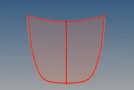
Fig: Checking of free edges.
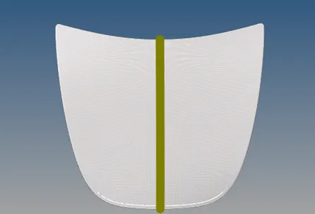
Fig: Equivalence of nodes.
23. Similarly check for duplicates to check go to Tools, check elements, Duplicates if found save failed, and delete them by selecting retrieve. Finally check for normal.
24. Switch to the inner panel mid surface start meshing from the inner most regions where the surfaces are fully enclosed and has no free edges.
25. Repeat the above mentioned procedures in order to maintain the quality of the elements. At the complicated locations add or remove some split lines and re-mesh the elements so that most the issues may fix.
26. Most of the elements at the fillet intersection will fail for maximum quad angle and warpage. To fix this change the element color mode to by element. Go to Tools, Translate, select the one node of the warped element and select N1, N2, and N3 (vector) as rest of the nodes of the same, set magnitude to 0.01 and translate in one direction and check for the reduction of warpage if not reverse the direction. To check the warpage value of individual component Go to Tools, Check elemets, select the elemets. While translating the nodes make sure that the surrounding surfaces were meshed.
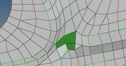
Fig: Warped elements.
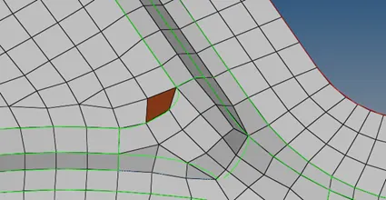
Fig: Max. Quad angle of element.
27. The max. or min. quad angle, max. or min. size of the element can be fixed by translating the nodes in a required direction. To check the sizes or angles between the nodes Go to Geom, Distance, for liner measurements use 2 nodes and for angular 3 nodes. Make sure that none of the elements are failing.
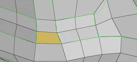
Fig: Failed element for Minimum element length.
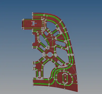
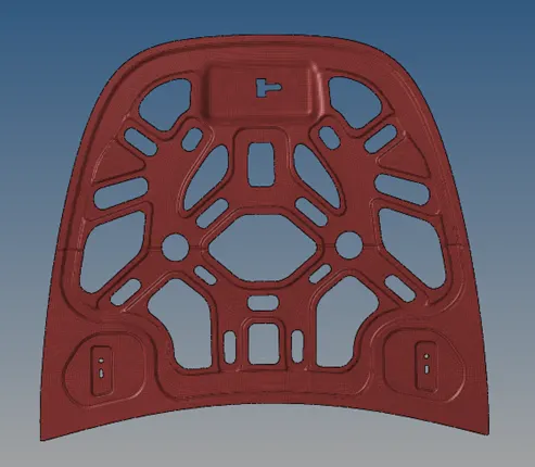
Fig: Meshed inner panel.
28. Once all the elements are fixed change mesh topology revision to keep mesh and reflect the surfaces by masking or de selecting the central common surface. Toggle the central lines.
29. Change the mesh topology revision to advanced re-mesh and reflect the elements.
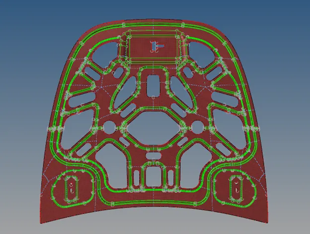
Fig: Meshed inner panel.
30. Check for normals also check for free edges if found equivalence them and check for duplicates and delete them by repeating the above mentioned procedures.
31. Still the free edges are present even after equivalence of the nodes then that need to be fixed manually by replacing the nodes. Go to 2D, Replace, select the nodes to be replaced.
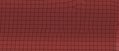
Fig: Mismatching of nodes.
RESULT:
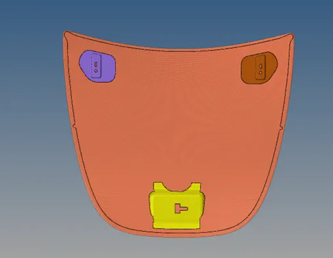
The given hood components were meshed to ideal levels without compromising the specified quality parameters and the feature capturing aspects.
MESHED HOOD COMPONENTS