Week 9-Challenge
AIM:
To Connect all the components which given in the model By, Using 1D or 2D Connectors in Hypermesh.
OBJECTIVE:
Deploying the connections between the different components in the given model by, Using 1D or 2D connectors i.e seam, spot, bolt, masses, adhesive etc. Make sure all the connectors get realised. After that check the mesh flow, which get disturbed due to connecting the components using connectors.
CONNECTORS:
Connectors are geometric entities, Which are primarly used to represent the cad geometric connection in terms of FEA. Connections can be created as a spot-weld, seam-weld,bolt,adhesive,masses. A realized connector will be consider as the successful representationof a CAD mode.
MODEL:
*The given frame model consists different components so, We can perform different connections Using different 1D or 2D connectors.
*Components list of a frame model, which shows in Fig(1):
i.Front Truss-1
ii.Front Truss-2
iii.Reinf plate
iv.Right Rail-1
v.Right Rail-2
vi.Left Rail-1
vii.Left Rail-2
viii.Rear Truss-1
ix.Rear Truss-2.
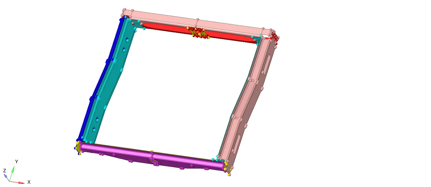
Fig(1).
PROCEDURE:
*In this model there are different type of connections are made to different components using sutable connectors.
1.Seam-Quad(angled+capped+L)
2.Quad elements
3.Spot weld
4.Hexa (Adhesive)
5.Bolt Connector
6.Spot-weld with Rigid Elements
7.Spot-weld with Spring Elements.
1.Seam-Quad(angled+capped+L):
* The process of joining the workpiece which are made of similar or diimilar materials along a continuous seam is known as seam weld.
*In the given model take 'Right Rail-2 and Front Truss-1' components to perform the seam-quad(angled+capped+L).
Steps to make seam-quad(angled+capped+L) connection:-
i.Create proper mesh and satisfy all the given criteria parameters.
ii.Go to seam option by, Selecting 1D/2D >> connectors >> seam.
iii.Select the type as "seam-quad(angled+capped+L)".
iv.Click the nodelist to Select the location, Where the welding has to be done.
v.check the retain nodes option, to retain the position of the nodes, While creating and realizing a connector.
vi.Specify the spacing value that defines the space between each node of the weld element, It should be equal to target element size, This will ease the weld element to be created between the components.
vii.Give the tolerance value, based on the distance between the joining components.
viii.Select the components which are going to get connect.
xi.Specify the Weld Angle, It is recommended to define weld angle between 0 to 90 degree.
x.Specify the Cap Angle, If weld angle is between 0 to 45 degree then select cap angle lessthan or equal to 10 degrees and for wel angle is between 45 to 90 degrees, cap angle is greaterthan or eual to 75 degrees.
xi.specify Runoff angle, It is recommended to define runoff angle between 0 to 10 degrees.
xii.After specifying all the required values then click on the create button, to create seam weld as shown in Fig(2).
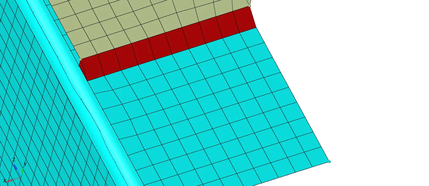
Fig(2).
xiii.After creating seam weld still the connectors are not realised then check the spacing value and tolerance value both are within the region or not.
xiv.If any unrealized and failed connectors are present in the connections make them realised or delete them in connector Panel.
xv.To go connector panel by, Selecting the View >> Browser >> Hypermesh >> Connector as shown in below Fig(3).
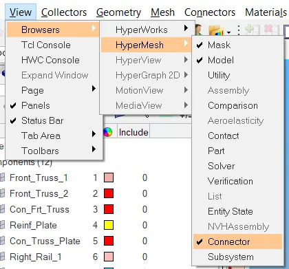
Fig(3).
2.Seam Quad elements:
*In the given model take 'Left Rail-2 and Front Truss-1' components to perform the seam-quad Elements.
Steps to make seam-quad Elements connection:-
i.Create proper mesh and satisfy all the given criteria parameters.
ii.Go to seam option by, Selecting 1D/2D >> connectors >> seam.
iii.Select the type as "seam-quads ".
iv.Click the nodelist to Select the location, Where the welding has to be done.
v.check the retain nodes option, to retain the position of the nodes, While creating and realizing a connector.
vi.Specify the spacing value that defines the space between each node of the weld element, It should be equal to target element size, This will ease the weld element to be created between the components.
vii.Give the tolerance value, based on the distance between the joining components.
viii.Select the components which are going to get connect.
ix.In this connection no need to mention weld angle,cap angle, runoff angle because the connection is done perpendicular to both the component planes with quad elements.
x.After specifying all the required values then click on the create button, to create seam weld as shown in Fig(4).
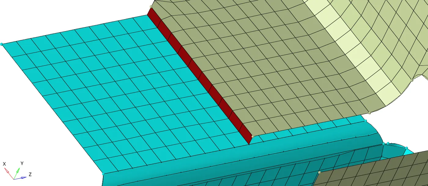
Fig(4).
3.Spot weld :
*Spot welding is a resistance welding process that is used primarily for welding the two or more metal sheets together by applying pressure and heat at the weld area. Heat for the welding process will be obtained from the resistance to electric current.
*In the given model take 'Right Rail-1 and Front Truss-1, Front Truss-2' components to perform the spot weld.
Steps to make spot weld connection:-
i.Create proper mesh and satisfy all the given criteria parameters.
ii.Go to spot option by, Selecting 1D/2D >> connectors >> spot.
iii.Select the type as "spot-weld".
iv.Click the nodelist to Select the location, Where the welding has to be done.
v.check the retain nodes option, to retain the position of the nodes, While creating and realizing a connector.
vi.Specify the spacing value that defines the space between each node of the weld element, It should be equal to target element size, This will ease the weld element to be created between the components.
vii.Give the tolerance value, based on the distance between the joining components.
viii.Specify the required number of layers and diameter value.
viii.Select the components which are going to get connect.
ix.After specifying all the required values then click on the create button, to create seam weld as shown in Fig(5).
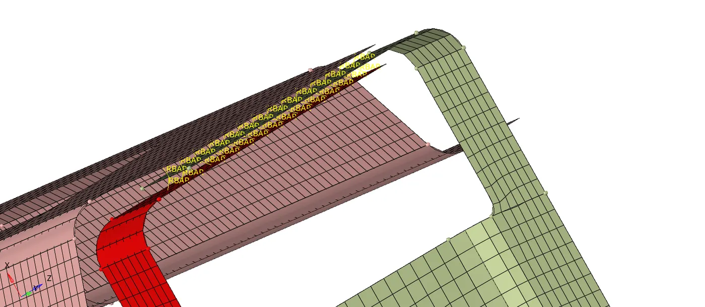
Fig(5).
*Here spot welding is carried with RBAR links as shown in above Fig(5).
4.Hexa (Adhesive):
*In the given model take 'Left Rail-1 and Front Truss-1,Front Truss-2' components to perform the seam- Hexa(adhesive).
Steps to make seam-Hexa(adhesive)connection:-
i.Create proper mesh and satisfy all the given criteria parameters.
ii.Go to seam option by, Selecting 1D/2D >> connectors >> seam.
iii.Select the type as "seam-Hexa(adhesive) ".
iv.Click the nodelist to Select the location, Where the welding has to be done.
v.check the retain nodes option, to retain the position of the nodes, While creating and realizing a connector.
vi.Specify the spacing value that defines the space between each node of the weld element, It should be equal to target element size, This will ease the weld element to be created between the components.
vii.Give the tolerance value, based on the distance between the joining components.
viii.Select the components which are going to get connect.
ix.After specifying all the required values then click on the create button, to create seam weld as shown in Fig(6).
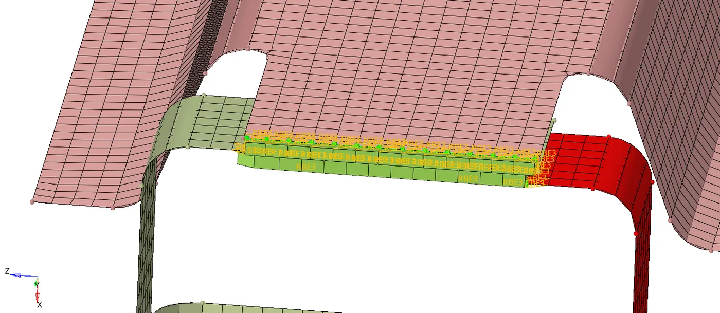
Fig(6).
*Here Hexa(adhesive) welding is carried with RBE3 links as shown in above Fig(6).
5.Bolt Connector:
*In the given model we have done two bolt connections one is between 'Left Rail-2 and Rear Truss-2' and one more between 'Rear Truss-2 and Right Rail-2' components to perform the Bolt connection.
Steps to make seam-Hexa(adhesive)connection:-
i.Create proper mesh and satisfy all the given criteria parameters.
ii.Go to seam option by, Selecting 1D/2D >> connectors >> bolt.
iii.Select the type as "bolt(general) ".
iv.Click the nodes to Select the location, Where the connection has to be done.
v.Specify number of layers to welded under 'num layers' option.
vi.Give the tolerance value, based on the distance between the joining components.
vii.Select the components which are going to get connect.
viii.After specifying all the required values then click on the create button, to create bolt connection as shown in Fig(7).
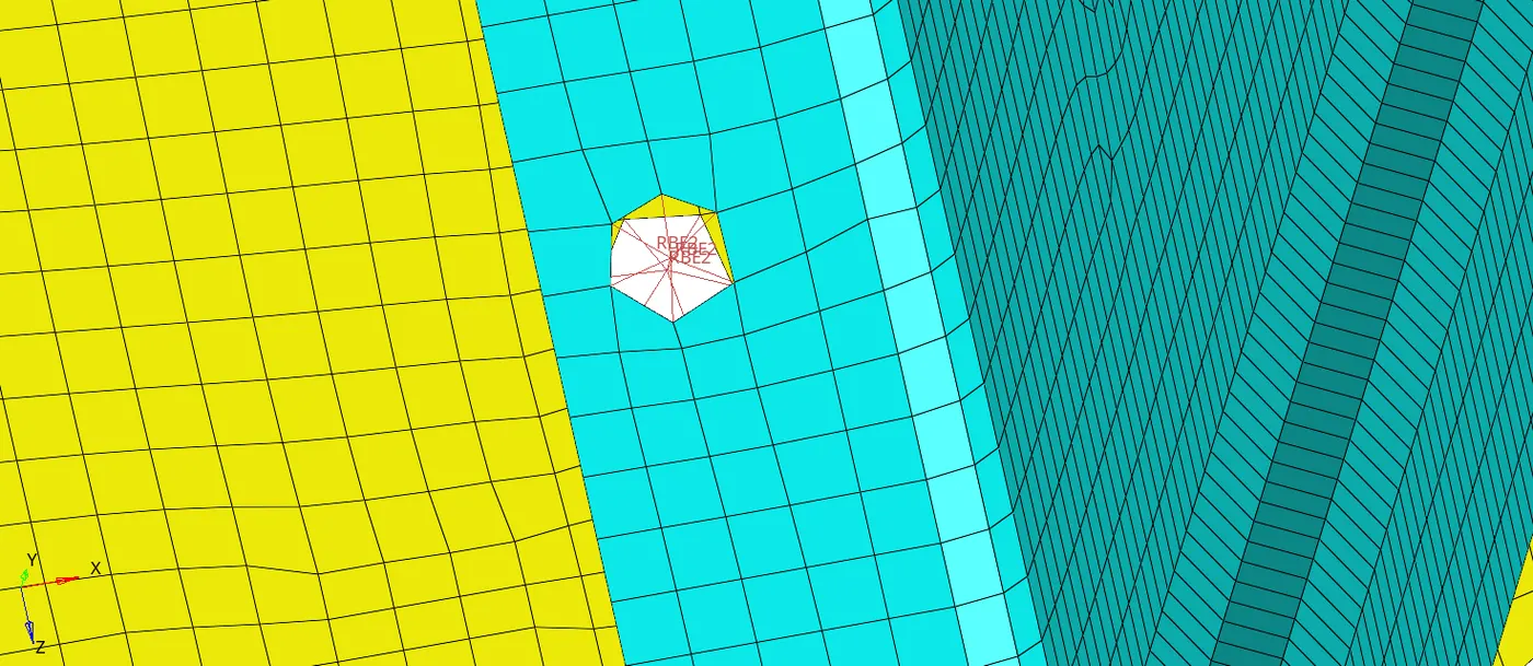
Fig(7).
*Here bolt welding is carried with RBE2 links (i.e rigid links ) as shown in above Fig(7).
6.Spot-weld with Rigid Elements:
*In the given model take 'Right Rail-1 andRight Rail-2 ' components to perform the spot rigid.
Steps to make spot rigid connection:-
i.Create proper mesh and satisfy all the given criteria parameters.
ii.Go to spot option by, Selecting 1D/2D >> connectors >> spot.
iii.Select the type as "spot-rigid".
iv.Click the nodelist to Select the location, Where the welding has to be done.
v.check the retain nodes option, to retain the position of the nodes, While creating and realizing a connector.
vi.Specify the spacing value that defines the space between each node of the weld element, It should be equal to target element size, This will ease the weld element to be created between the components.
vii.Give the tolerance value, based on the distance between the joining components.
viii.Specify the required number of layers and diameter value.
viii.Select the components which are going to get connect.
ix.After specifying all the required values then click on the create button, to create seam weld as shown in Fig(8).
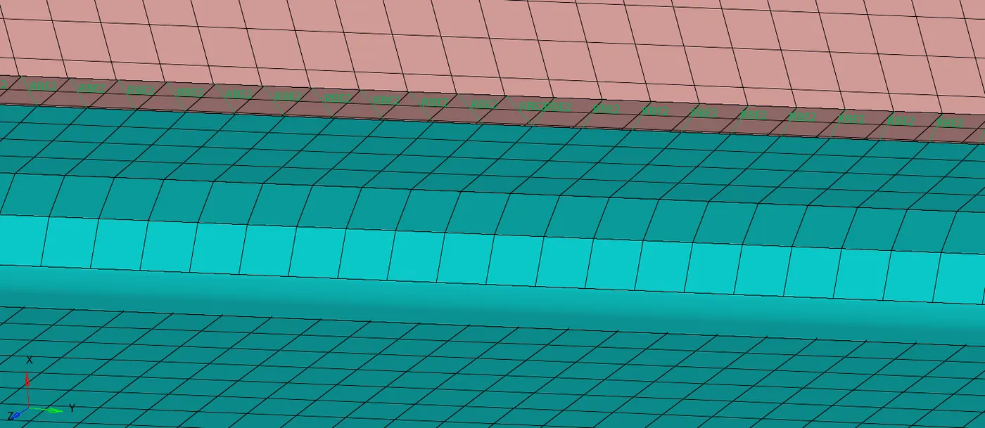
Fig(8).
*Here spot welding is carried with RBE2 links (i.e rigid links ) as shown in above Fig(8).
*spot weld with Spring elements is almost smiliar to spot weld with rigid elements but instead of rigid RBE2 links here CELAS1 links created as shown in Fig(9).
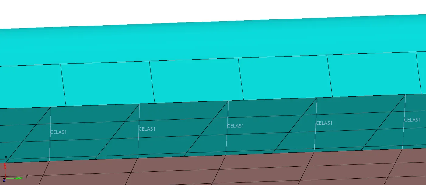
Fig(9).
RESULTS:
*All above mentioned procedures is used to make connections between the components present in given frame model using different 1D/2D connectors as shown in Fig (10).
*Connectors are geometric entities, Which are primarly used to represent the cad geometric connection in terms of FEA.
*FILE_NAME:FRAME09.hm
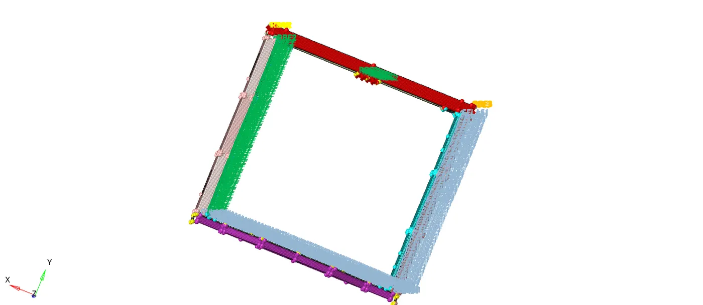
Fig(10).
*Above Fig(10) showns all the connections made in the frame model using different connectors.