Week 12 - Project-1
AIM:
To Generate the mid-surface and geometry clean up on the given, Side door plastic component of the car and assign proper thickness.
OBJECTIVE:
Make the proper segmentation of the given model, Which is used to smiplify the geometry to Extract the midsurface of the different components in the Side-door model manually. After that go for mesh by applying given criteria parameters and correct the failed elements, by using quality criteria tools. Finally create the material card, property card and assign the thickness for the all the components.
SIDE DOOR MODEL:
*A Vehicle door can be opened to provide access to the opening, or closed to secure. Side doors can be opened manually or powered electroniclly.
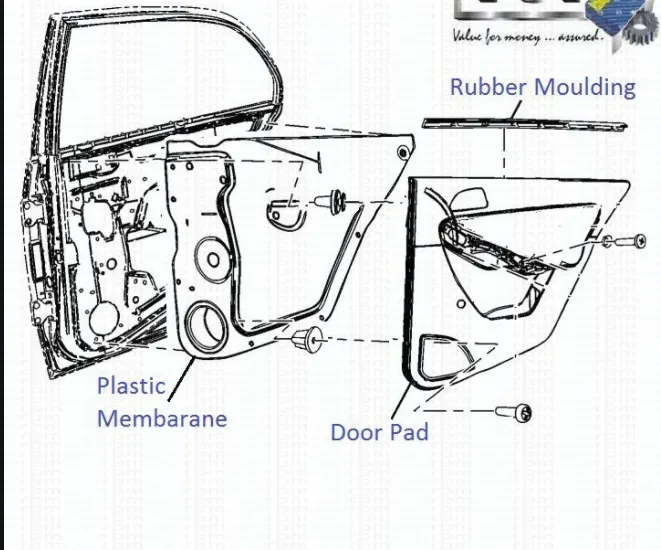
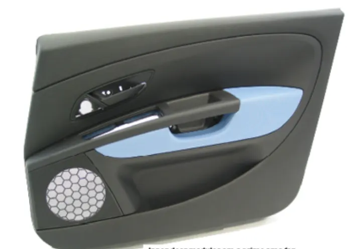
*Different parts in side door as shown in Fig(1) and Fig(2) shows how side door looks from inside.
Fig(1) Fig(2)
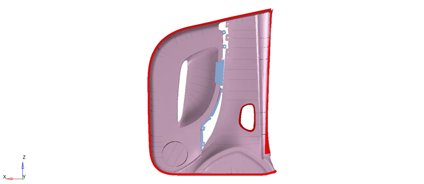
GIVEN MODEL:
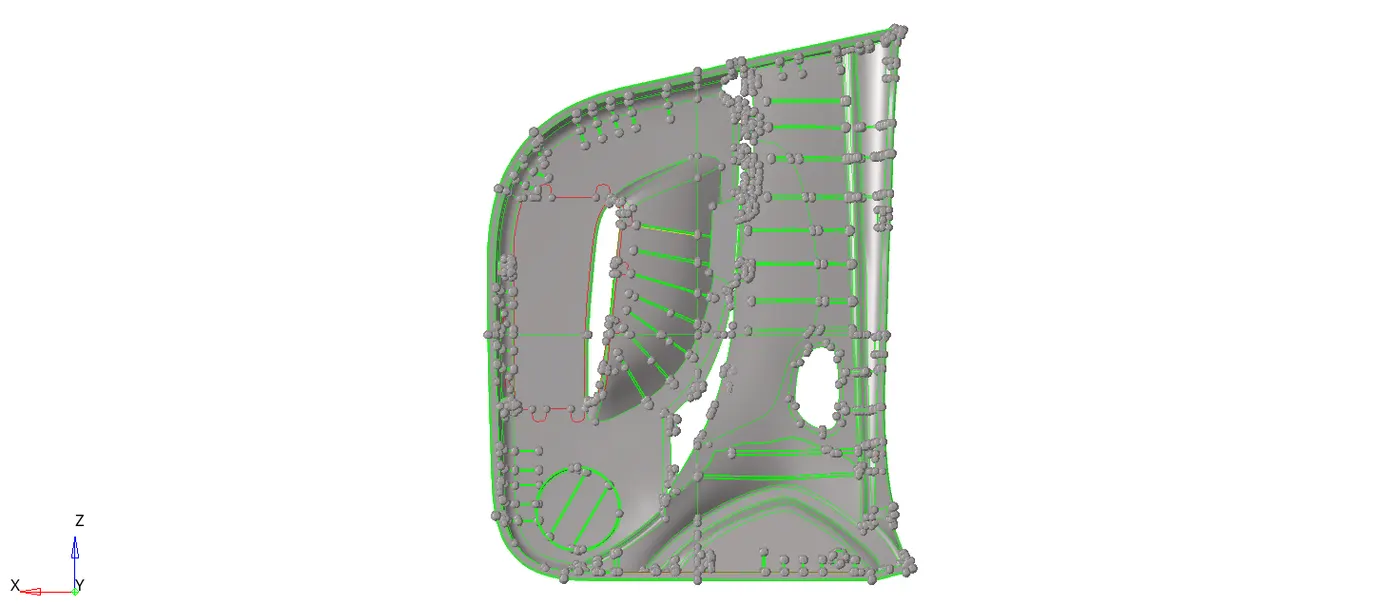
Fig(3).
PROCEDURE:
1.Import the geometry into hypermesh by, Selecting the File >> Import >> Geometry.
2.After importing the geometry check the thickness of the component using the distance option.
3.If you find the thicknesss is varying between one component to another component, It is better to Extract the midsurface manually, By offsetting the surface from the parent geometry to current component by duplicating the offsetting surface.
4.Extract the midsurface manually by, Selecting the Geom >> surface edit >> offset.
5.Better to select the all the outer surfaces to extract the midsurface then go for different inner components.
6.Extend all the ribs midsurfaces to the outer surface to get proper mesh flow.
7.Once extracting the midsurfaces from outer surfaces then extract midsurface for inner ribs, Which are shown in Fig(4).
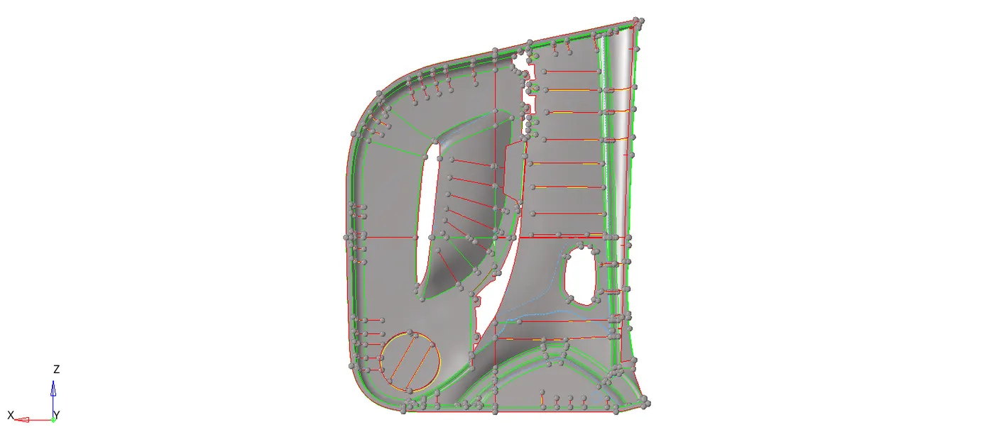
Midsurfaces of four parts Fig(4)
8.After extracting all the midsurfaces fro mthe component then create the mesh by applying the criteria file settings.
9.Creating the criteria files with required the parameters by, Selecting the preferences >> criteria file settings >> apply >> ok.
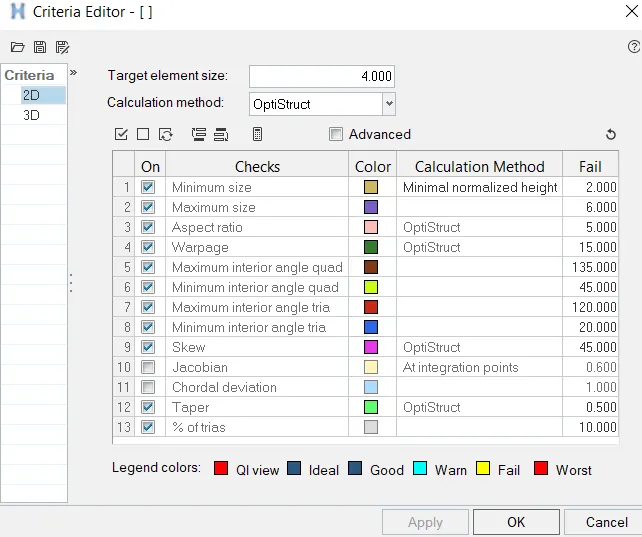
Criteria file settings Fig(5)
10.After creating criteria file setting then start meshing the components using automesh option in 2D panel by, Selecting the 2D >> automesh >> mesh.
11.After completing the mesh on one surface then go for quality check for the same surface to avoid the failed elements.
12.After removing all failed elements in that particular surface then go for next surface and perform the same operation to all the components.
13.There are some critical regions were elements get failed those are get fixed with quality index option by, Selecting the 2D >> quality index.
14. After completing quality check then go for proper mesh flow.By find free edges between the mesh (Tool >> edges >> find edges).
15.We have to correct the mesh flow by giving equvalance (Tool >> edges >> euivalance).
16.After giving euivalance still is there any free edges in between the meh lines then, we have fix those by manually uing replace tool.
13.Do the same process for all the components to get good mesh flow as shown in below Fig(6).
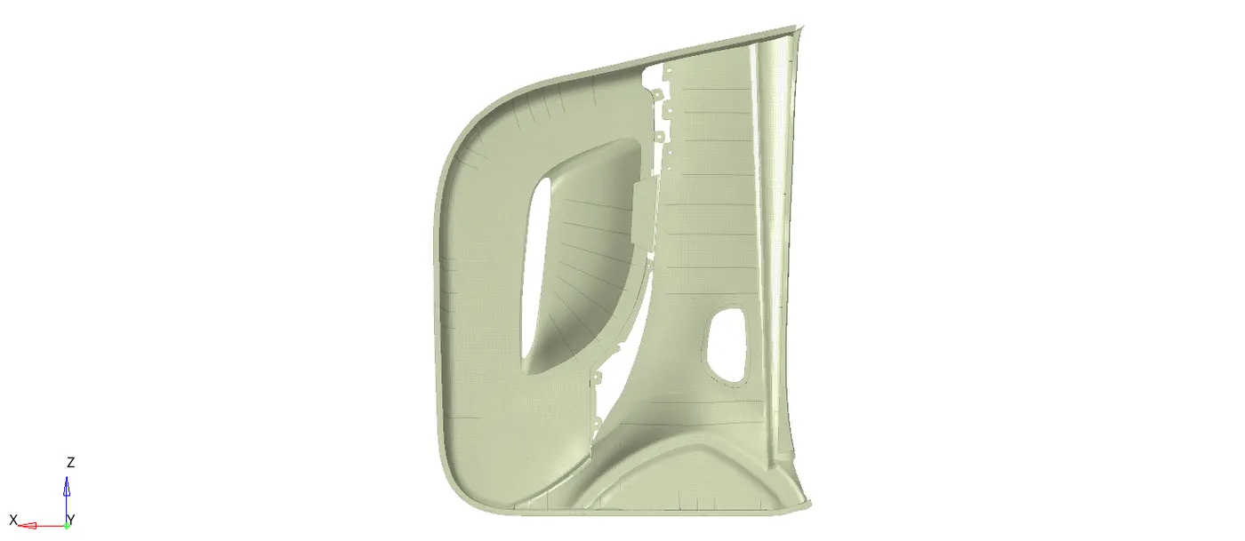
Mesh on sidedoor model Fig(6).
14.Check the mesh quality using quality index option in 2D panel as shown in below Fig(7).
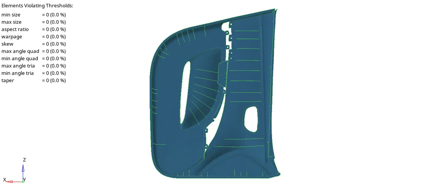
Quaality check Fig(8).
15.After complete the mesh and mesh flow then assign the material and thickness to all the components accordingly.
16.Select the material as steel with material card is 'MAT1' and create the properties with property card is 'PSHELL' to all the different thickness components.
17.To assign the thickness for particular component, First select all the elements in that component and collect those elements into different component collector and assign proper thickness property as shown in below Fig(9).
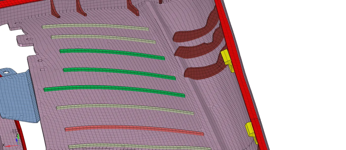
Different thickness components Fig(9).
18.Do the same process to get the good mesh flow on the components which are having the varying thickness (plastic components) and assign thickness to them.
RESULT:
*Extracting the midsurface to the components which are having varying thickness using the auto midsurface option. That midsurface is not acceptable because it creates lot of geometry changes.
*In such cases manual midsurface is better option to extract the midsurfaces for all the inner and outer components separately step by step and perform the geometry clean up .
*After that assigning the thickness to all the components accordingly as shown in Fig(10).
RESULTANT MESH Fig(10).