GENERATING 3D TETRAMESH ON THE GIVEN MODEL
AIM:
Generate the 3D Tetra Mesh on the given models by performing different 3D Tetra meshing methods.
OBJECTIVE:
In General 3D elements are two types Tetra and Hexa. 3D Tetra elements are widely used in industry because, it is easy to mesh complex geometry. There are Three different methods to perform 3D tetra mesh in Hypermeh software. Using those methods create the 3D tetra mesh on the given model under given criteria parameters.
Tetra Meshing:
Creation of tetrahedral elements on the given geometry by converting 2D tria elements into 3D terta elements.
*Methods to create Tetrahedral elements:
1.Conversion of 2D tria elements to Tetrahedral elements by using Tetra Mesh Panel.
2.Using Quick Tetra mesh, from Utility Panel.
3.Using Volume Tetra Mesh Panel.
*After performing above methods to create 3D tetra mesh remove the elements, which are failed under tet collapse.
Tet Collapse:
*Tet collapse is one of the quality prameters, Which will be checked while generating the tetradhedral elements.
*It can be calculated using the formula =min(h/squre root of the opposite face area (A)).
*h is distance between node (N1) and its opposite face, A is the area of opposite plane to node N1.
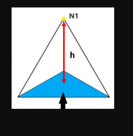
Fig(1).
PROCEDURE:
1.Conversion of 2D tria elements into Tetrahedral elements by using Tetra Mesh Panel:
i.import the model into hypermesh, by selecting the File >> Import >> Geometry options.
ii.Delete the solids in the model, by selecting the Delete >> Solid >> Delete entity.
iii.Make the proper geometry cleanup on the model as shown in Fig (2).
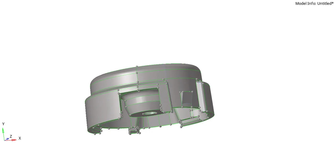
Fig(2).
iv.Specify the required criteria parameters in the preferences.
v.Create 2D Mesh with tria elements in 2D Panel, by selecting 2D >> automesh >> mesh.
vi.After creating the 2D mesh go to qulity index and check the elements, which are getting failed under maximum and minimum trai size.
vii.Eliminate the failed elements by optimising the elements as shown in Fig(3).
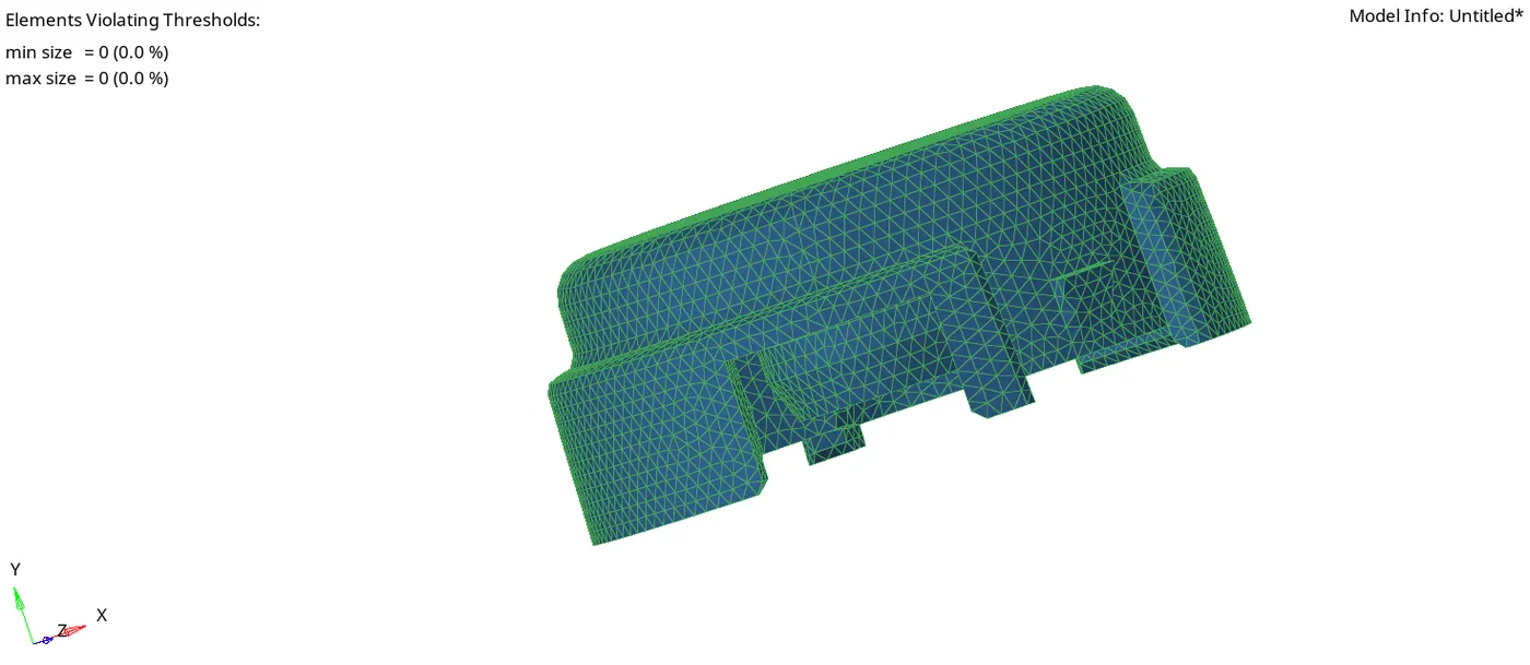
Fig(3).
viii.After that, create the 3D Tetra mesh using the Tetra mesh option in 3D Panel, by selecting the 3D >> tetramesh >> Tetra Mesh.
ix.check any 3D tetra elements get failed under the tet collapse parameter by selecting Tool >> check elems >> 3d >> tet collapse.
x. Number of elements failed is shown in status bar. We can rectify those elements by following two methods
1. Using translate option to increase the height of the tetra element.
2. Using the Tetra remesh Panel, To remesh the failed elements.
2.Using Quick Tetra mesh, from Utility Panel:
i.import the model into hypermesh, by selecting the File >> Import >> Geometry options.
ii.Delete the solids in the model, by selecting the Delete >> Solid >> Delete entity.
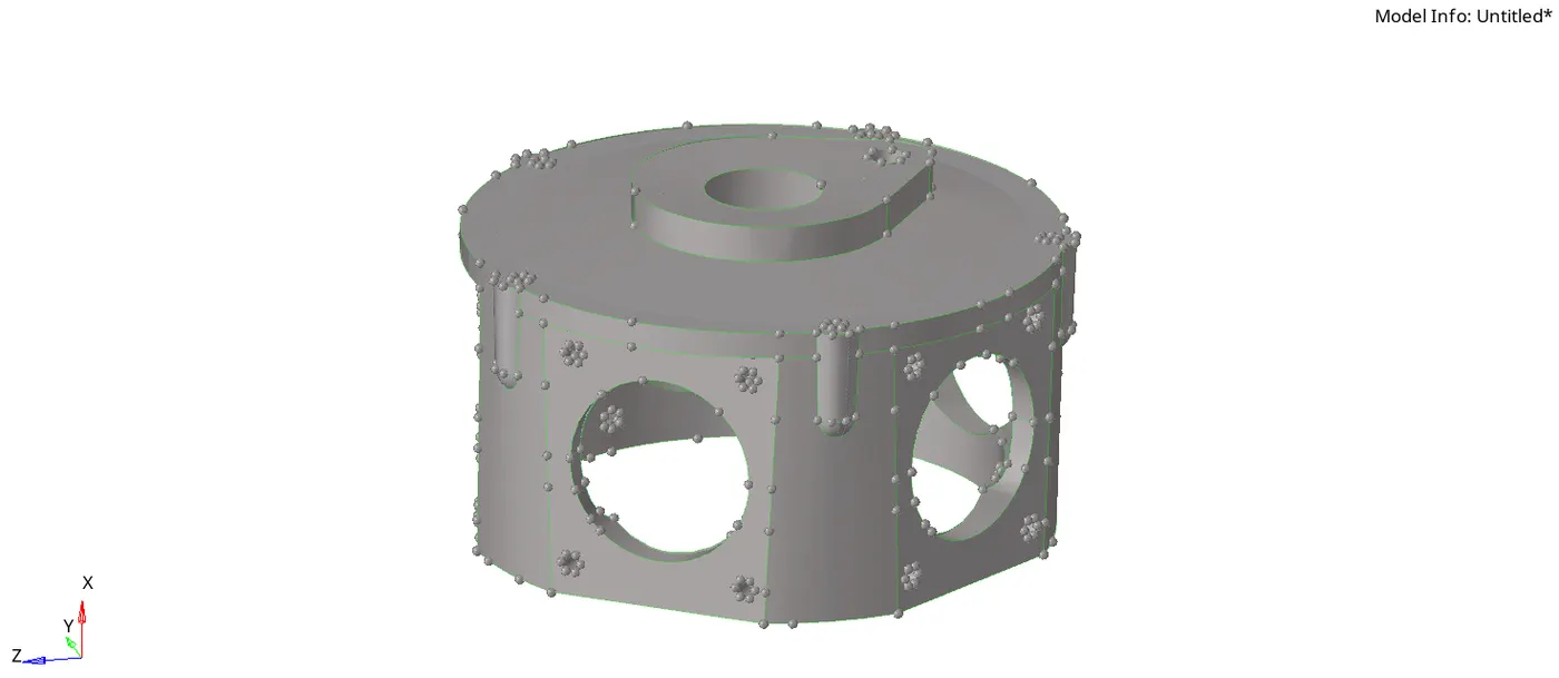
Fig(4).
iii. Go to Quick Tetra mesh panel, by selecting the View >> Browser >> Utility. In Utility Panel click on Geom/Mesh then choose Quick Tetra Panel.
iv.In Quick Tetra mesh Panel assign the Mesh size and type of elements (i.e tria or quads) .
v.Select the component and click on the mesh to create both 2D and 3D meshing on the given component.
vi. All the 3D elements are collected into saperate collector.
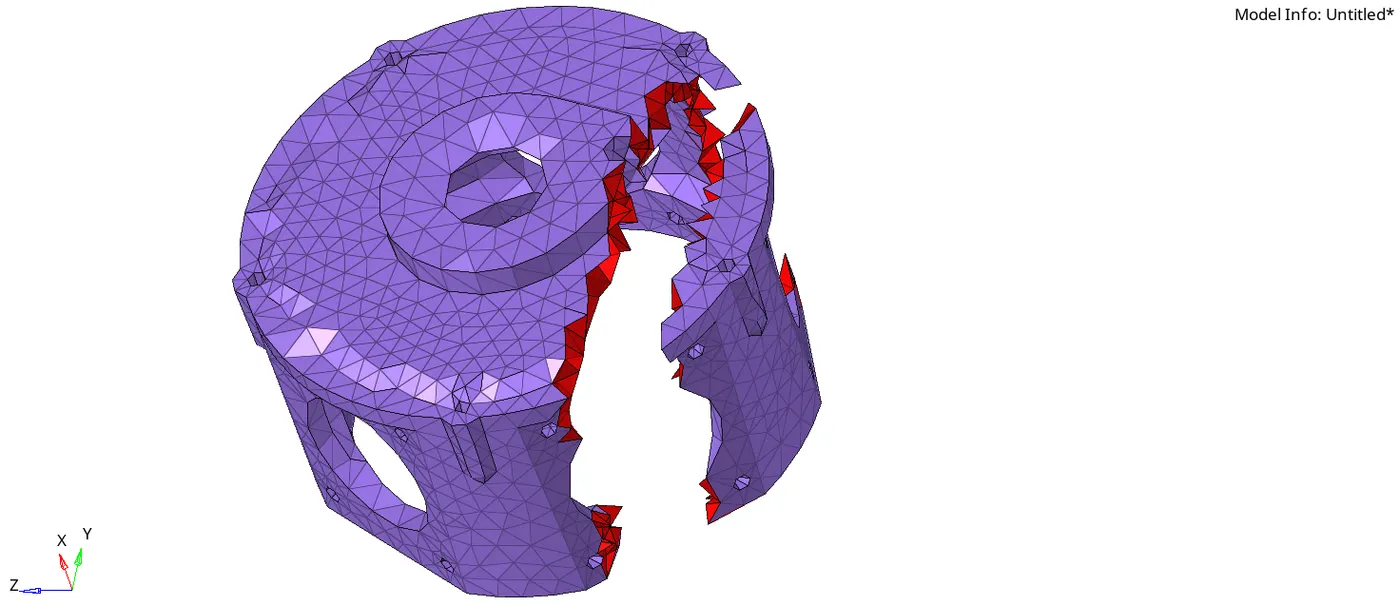
Fig(5).
vii.check any 3D tetra elements get failed under the tet collapse parameter by selecting Tool >> check elems >> 3d >> tet collapse.
3.Using Volume Tetra Mesh Panel:
i.import the model into hypermesh, by selecting the File >> Import >> Geometry options.
ii.Don't delete the solids in this process.
iii.Perform the volume tetramesh using 3D panel, by selecting the 3D >> tetramesh >> Volume tetra.
iv. select the solids and click on the mesh to create the 3D Tetra mesh. In Fig(6) clearly shown the 3D tetra elements by masking few surface elements.
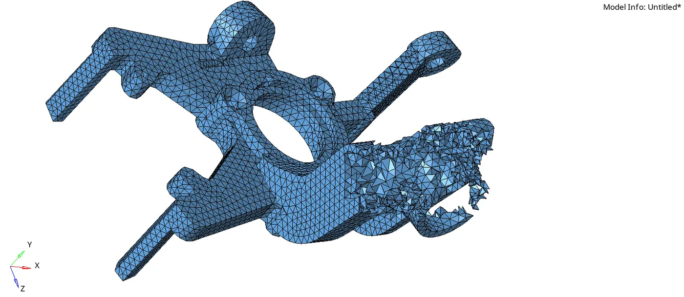
Fig(6).
v.After creating 3D volume tetra mesh, check any 3D tetra elements get failed under the tet collapse parameter by selecting Tool >> check elems >> 3D >> tet collapse.
* Above all three methods used to create the 3D tetra elements. The elements which get failed under the tet collapse can be rectified by using manual or remesh methods.
Methods to Remove tet Collapse:
1. Using translate option to increase the height of the tetra element:
i.After creating the tetra mesh, Check for the failed elements.
ii.Select Tool >> Check elems >> tet collapse.
iii.In status bar it will show how many failed elements are present in the model.

iv.Remove the tet collapse, by selecting the Tool >> translate option.
v.pick a node in any one failed element, Which has minimum height.
vi.Give rondom magnitude values approximately by trail and error method.
vii.Click on the translate button to move the node.
viii.After correcting the failed element,parallelly check the tet collapse value in the Check elems command.

ix. by following above process we can eliminate all the failed elements.
2. Using the Tetra remesh Panel, To remesh the failed elements.:
i.After creating the tetra mesh, Check for the failed elements.
ii.Select Tool >> Check elems >> tet collapse.
iii.In status bar it will show how many failed elements are present in the model.
iv.Perform the Tetra remesh in tetramesh Panel, by selecting the 3D >> tetramesh >> Tetra remesh.
v. Before to do remesh specify the tet collapse value in tetramesh parameters.
vi.Now go to Tetra remesh and select all the 3D and 2D elements and click on remesh ( select 3D and 2D elements for first two methods only).If the 3D mesh is done by using volume tetra then select only 3D elements and do remesh.
v.By performing remesh we can remove all the failed elements.
RESULTS:
1.Conversion of 2D tria elements to Tetrahedral elements by using Tetra Mesh Panel:
*This process is used when we reuired more control over the mesh and to get the better aprroximation solution.
*It is time consuming process.
*FILE_NAME:3DHousing_.hm.
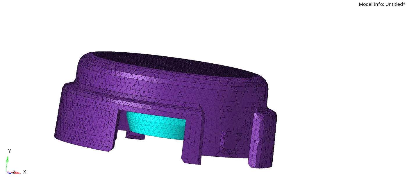
Fig(7).
2.Using Quick Tetra mesh, from Utility Panel:
*This process used to get rough mesh without proper mesh control.
*Time required to mesh is less.
*In this method 3D tetra elements can stored in different component collector.
*FILE_NAME:3D_i_.hm.
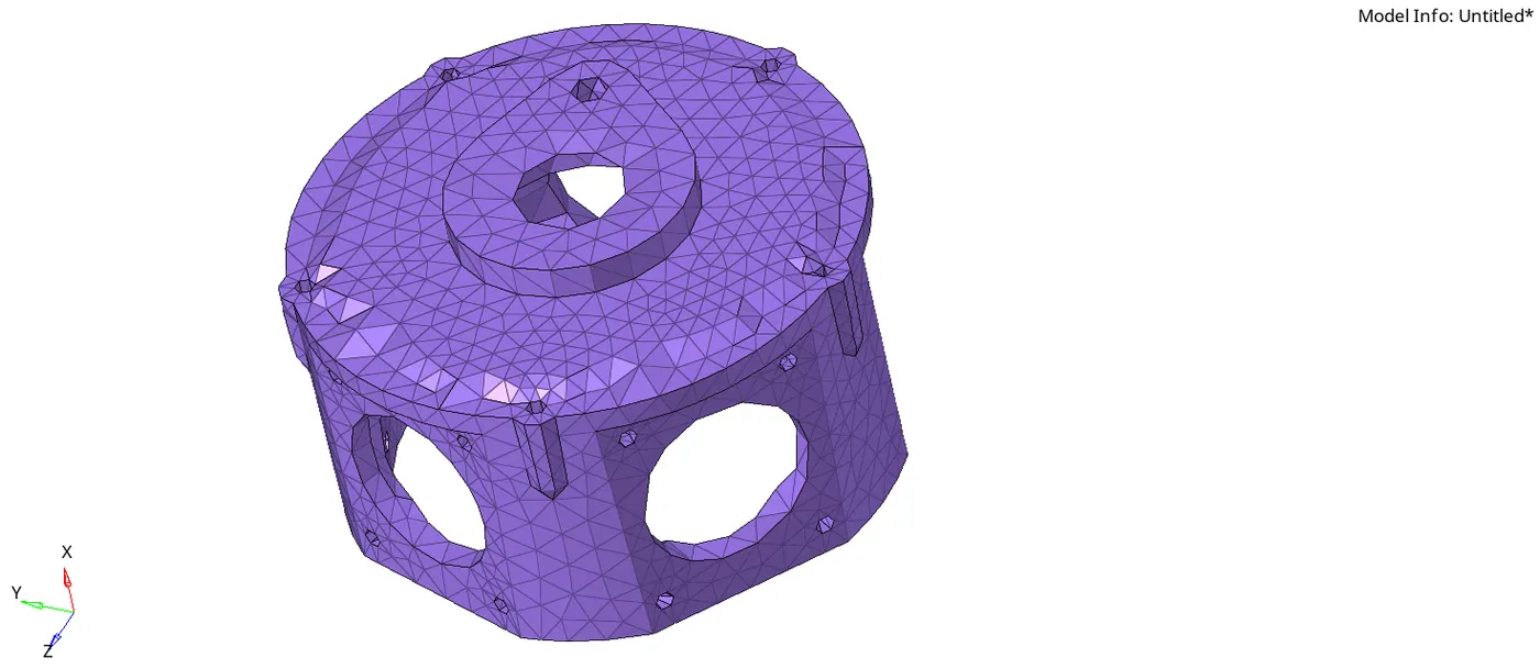
Fig(8).
3.Using Volume Tetra Mesh Panel:
*This process used to get rough mesh without proper mesh control.
*Time required to mesh is less.
*In student version if elements get crossed above one lakh the file would not be saved.
*Since this component is symmetric about y-axis, I meshed only half part. By using reflect option in Tool Panel we can get full component mesh.
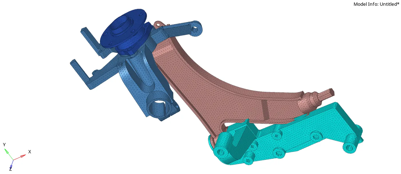
*FILE_NAME:chassis.hm