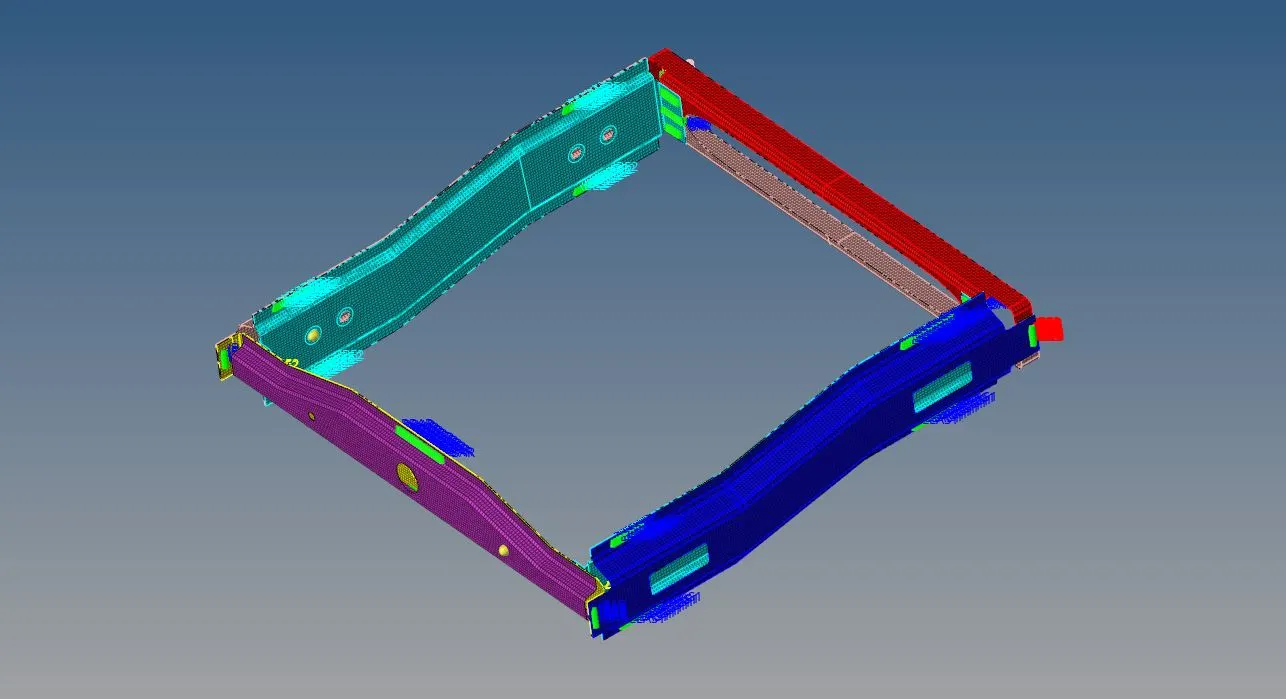
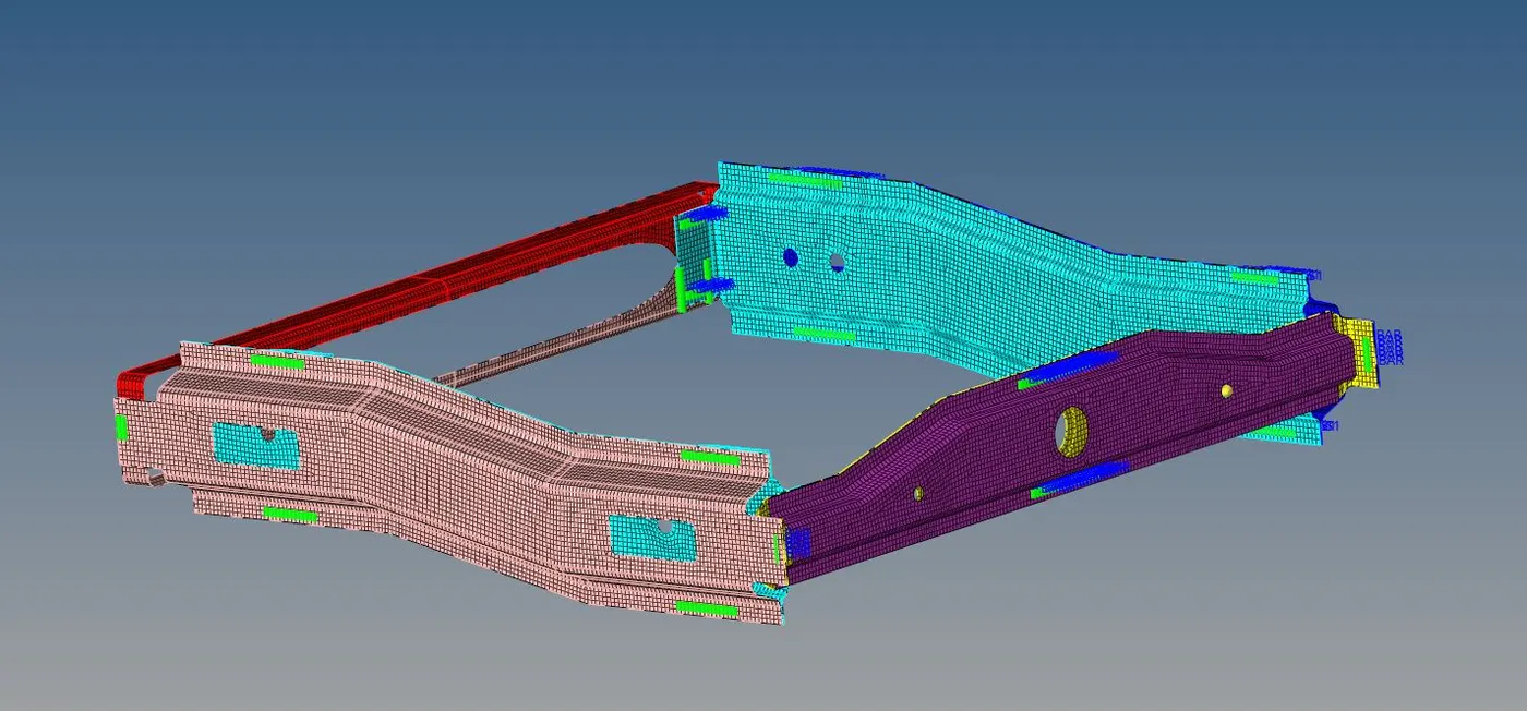
Week 9-Challenge
Objective: Connect the frame components in the FEA form with the use of the mentioned connectors in realized form.
Definition: connectors are used to connect two components in the pre-processing of the geometry. There are various types of connectors present in the Hypermesh software i.e. Bolt, seam, weld, etc. and each of them has various forms that are mentioned in the procedure.
Cad Model Image:
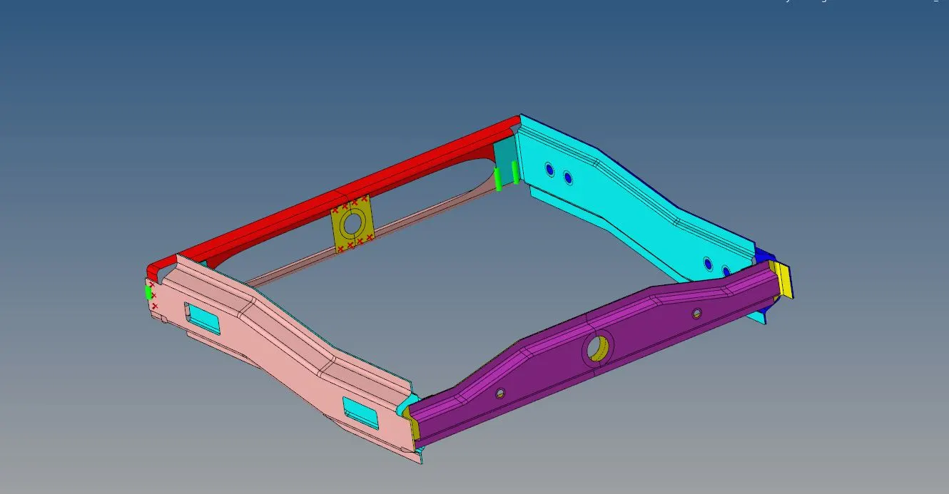
Procedure:
- All the parts are meshed using the mixed element type by keeping the target element length as 5mm
- Back to back, opposite triangles have been removed and the geometry is cleared in terms of the quality.
Connector 1: Seam-Quad (Angled + Capped + L)
- To connect the right rail 2 and front truss 1 using it is started as, inside the connector option of the 1D menu the seam option has been selected by selecting the mentioned seam type.
- In this, the spacing value has been set to 5 as the meshing size is 5 by keeping the option retain nodes checked. The tolerance value has been set to 40 to realize the respective nodes.
- The specification of the run-off angle, cap angle, and the weld angle is kept to default value.
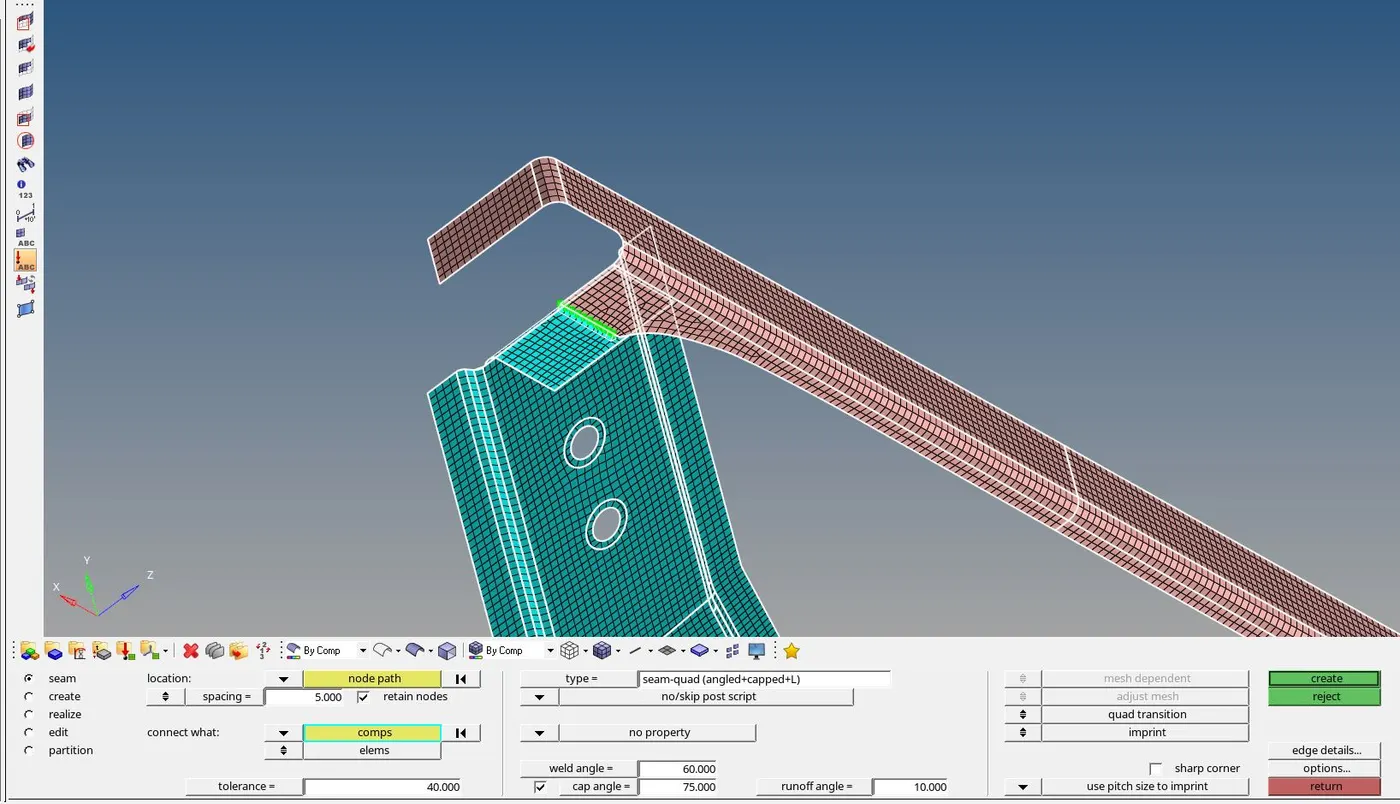
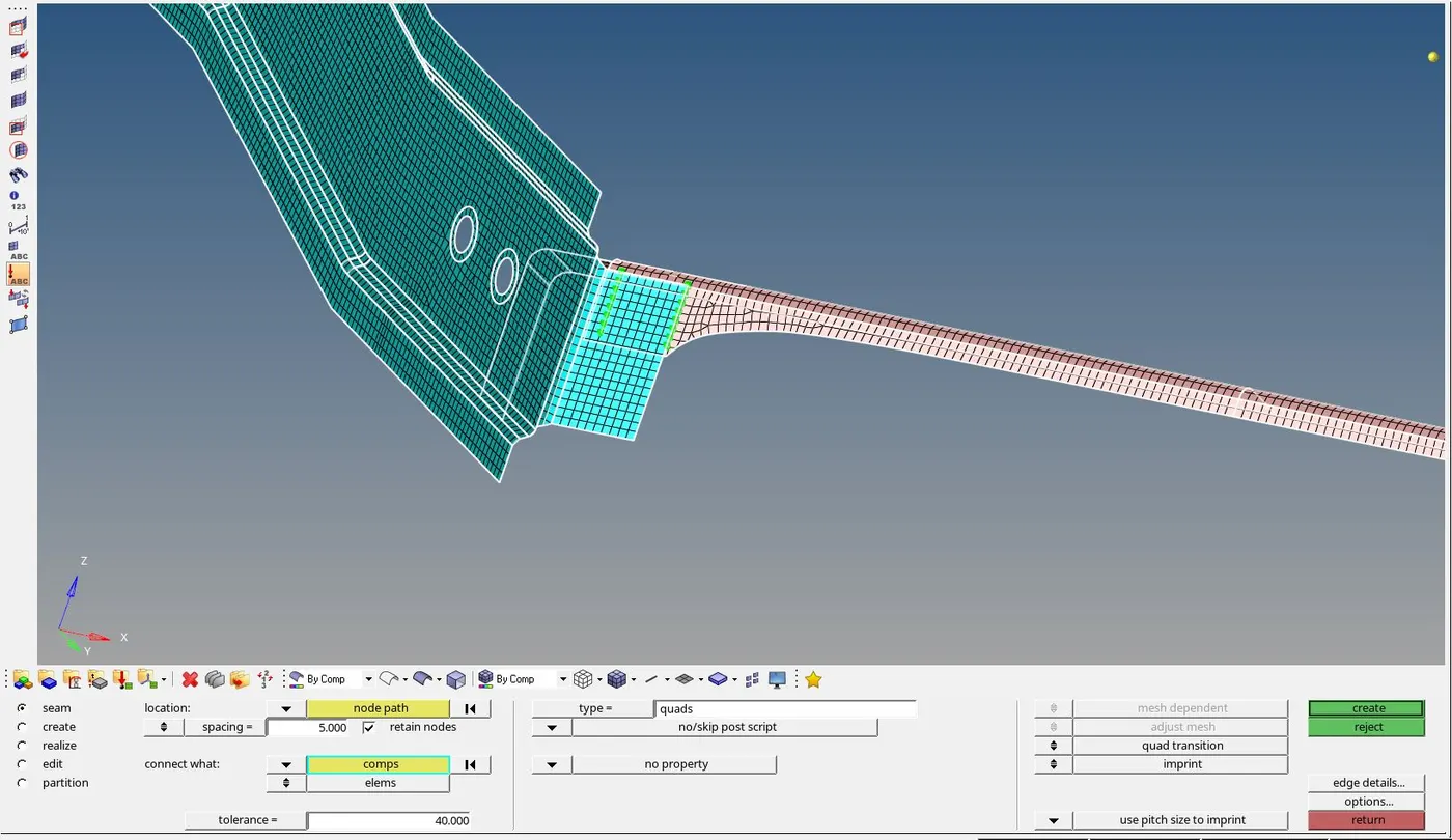
Connector 2: Quad Elements
- For quad element connector the left rail 2 and front truss 1 component has been selected and the quad element connector has been selected under the seam column and the rest of the options are set as mentioned the 1st connector.
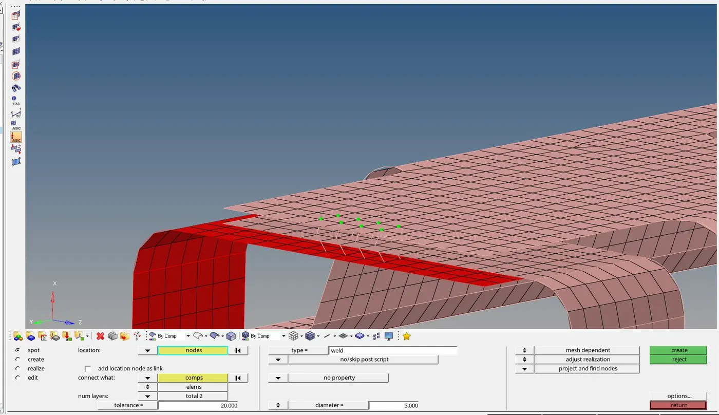
Connector 3: Spot Weld
- The components Front truss 2, Front truss 1, and the right rail 1 are connected by selecting the option Spot in the 1D element and the respective nodes have been selected by defining the diameter size as 5mm and the no of layers has been set 3 to perform the spot weld for all three surfaces.
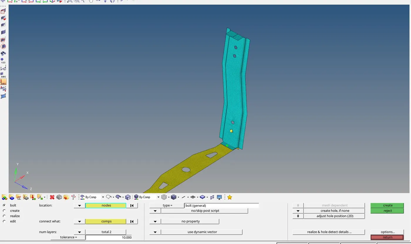
Connector 4- Bolt Connector
- The component Rear truss 2 and the right rail 2 both are connected by selecting the option bolt from the 1D menu.
- In the bolt option, a single node has been selected by selecting the connecting components and keeping the tolerance value as 10.
Connector 5 & 6- SpotWeld with Rigid and Spring Elements
- The component right rail 1 and 2 are connected by selecting the options spot from the 1D element and then from the type of element dropdown menu rigid type has been selected
- Similarly, for the left rail 1 & 2 instead of rigid elements, the spring elements have been selected.
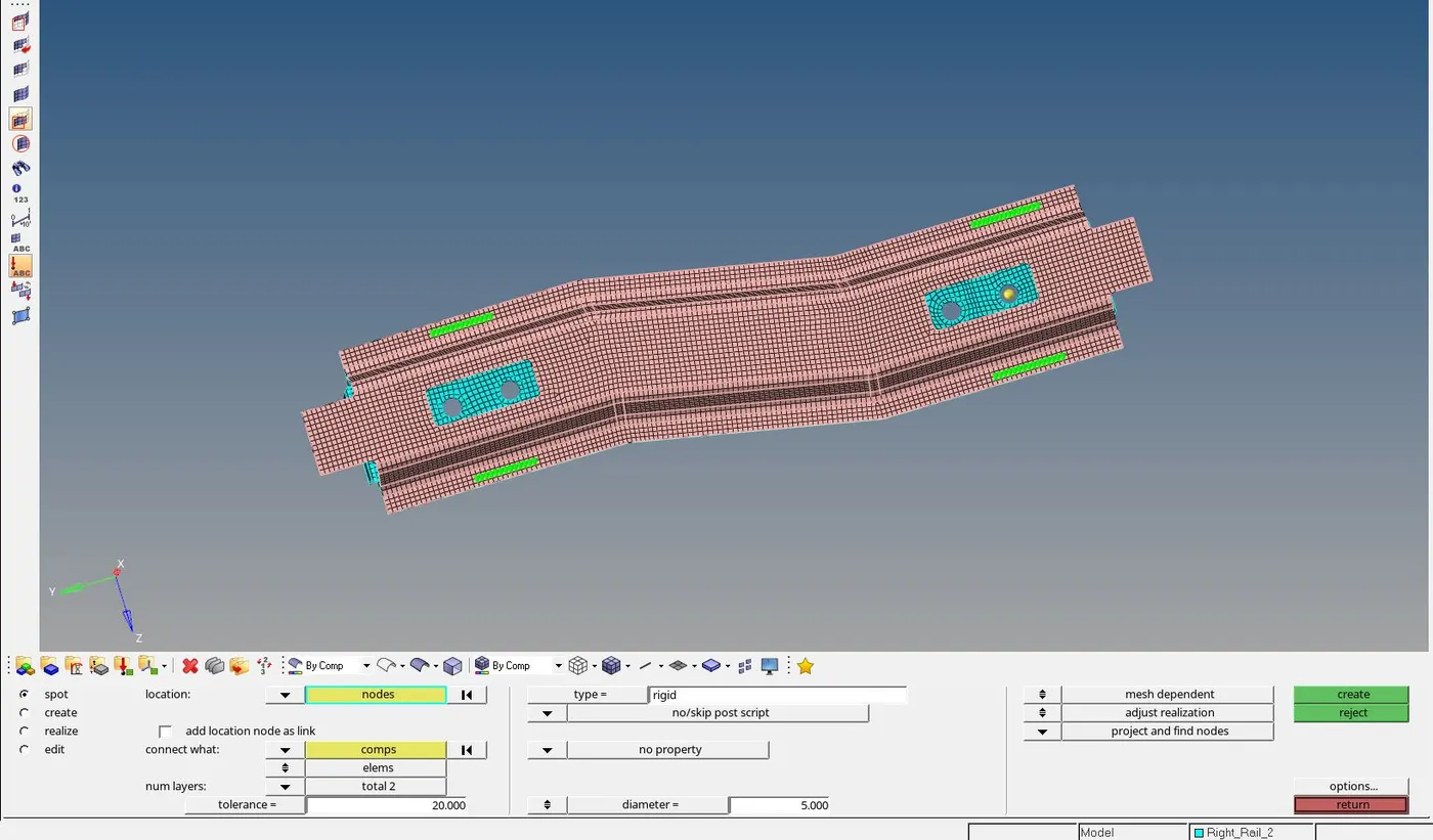
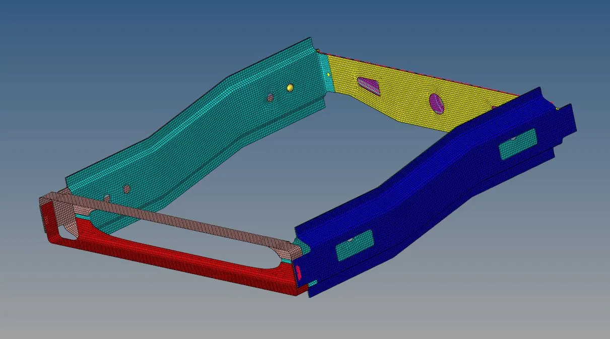
Rest all the connections have been done using the spot weld method since this method is commonly used to connect two metal sheets.
Final Model Image: