Week 9 Challenge
AIM OF THE EXPERIMENT: To determine the wave load acting on the bridge model and perform analysis Staad.Pro.
THEORY:-
Wave loading is most commonly the application of a pulsed or wavelike load to a material or object. This is most commonly used in the analysis of piping, ships, or building structures which experience wind, water, or seismic disturbances.

Centre of Gravity:-The centre of gravity is a point in an object where the distribution of weight is equal in all directions, and it does depend on the gravitational field. However, an object's centre of mass and centre of gravity lies at the same point in a uniform gravitational field.
Centre of Buoyancy:-The centre of buoyancy is the centre of gravity of the volume of water displaces by the body when immersed in the water.
Given Data :
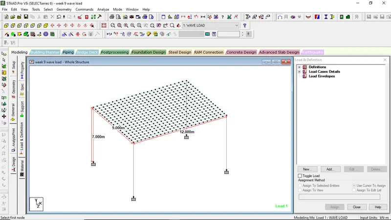
Span of bridge = 12.0 m
Width of carriage way = 9.0 m
Maximum crest elevation = 3.0 m
Number of Main Girders = 3
Thickness of deck slab = 2.0 m
Constant r = 5
Coefficient of varying load (Cva) = 3
Storm elevation = 8.5 m
Reduction Coefficient (Cr) = 0.4
Assumption:
Size of Pier = 2.5 m Dia.
Height of Pier = 7m including pier cap
Size of Cross beam = 1 m x 1.5 m
Calculations:
Maximum elevation of wave crest, ηmax = 8.5 + 3 =11.5 m (storm elevation +3m for max crest elevation)
Depth of Superstructure = 2 + 1.7 = 3.7 m
ΔZh = ηmax – Centroid of superstructure = 11.5 – ((3.7/2)+7) = 2.65 m
ΔZv = ηmax – elevation of upside of deck =11.5 – (2+1.7+7) = 0.8 m
Number of girders (N) = 3
Vertical load (Fv) = r x ΔZv x Av = 5 x 0.8 x (9 x (3.7/2)) = 66.6 KN
Horizontal load (Fh) = r x ΔZh x Ah = 5 x 2.65 x (12 x 3.7) = 588.3 KN
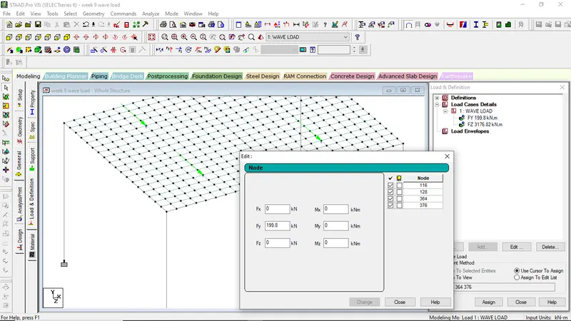
Maximum wave induced vertical load (Fvmax) = Cva x Fv = 3 x 66.6 = 199.8 KN
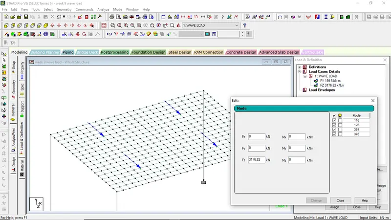
Maximum wave induced horizontal load (Fhmax) = (1+Cr x (N-1)) x Cva x Fh = (1 + 0.4 x (3-1)) x 3 x 588.3 = 3176.82 KN
PROCEDURES IN STAAD PRO
STEP 1:-
Model the Structure as given in the question
STEP 2:-
Assign the property to the elements of structure
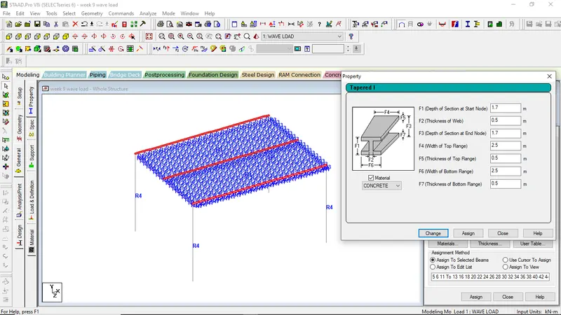
For main girders, dimensions are given in the question
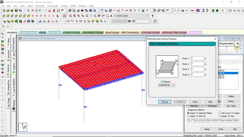
For deck slab elements hickness provided=2m
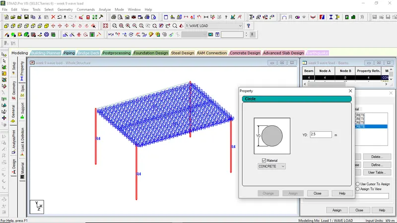
For Pier Elements, Height=2.5m
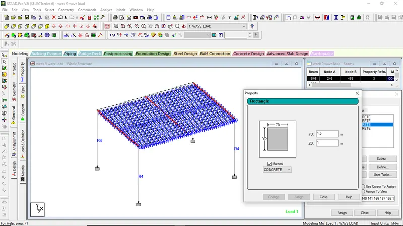
For cross-girder, rectangular size= 1m x 1.5m
STEP 3:-
Giving support conditions to the structure
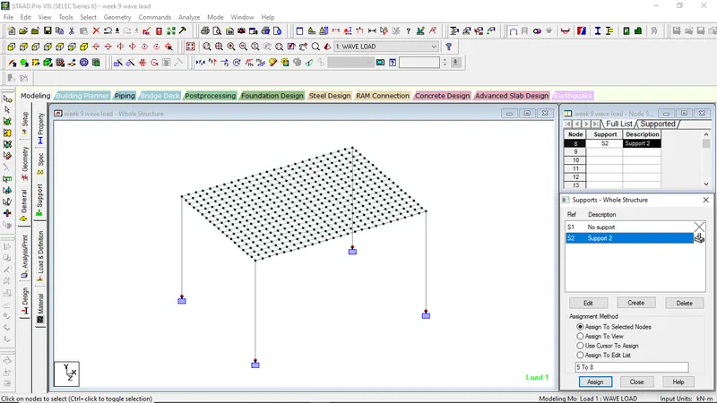
STEP 4:-
Application of Wave loadings to the Bridge Structure:-
- Go to Loads and Defination
- Click on Load case Details
- Rename as Wave loads
- Select wave loads
- Go to the Nodal loads
- Put the (Fvmax)=199.8KN in Fy direction
- Put the (Fhmax)= 3176.82KN in Fz direction
STEP 5:-
Analyzing the Structure
- Go to Analasys/Print
- Select No Print
- Go to Analyze Menu
- Select Run Analysis
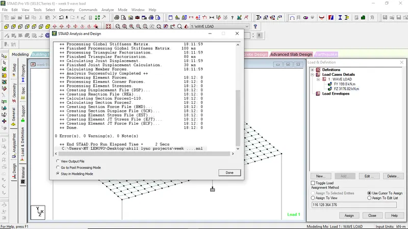
STEP 6:-
Go to Post Processing Mode to get the desired analytical results
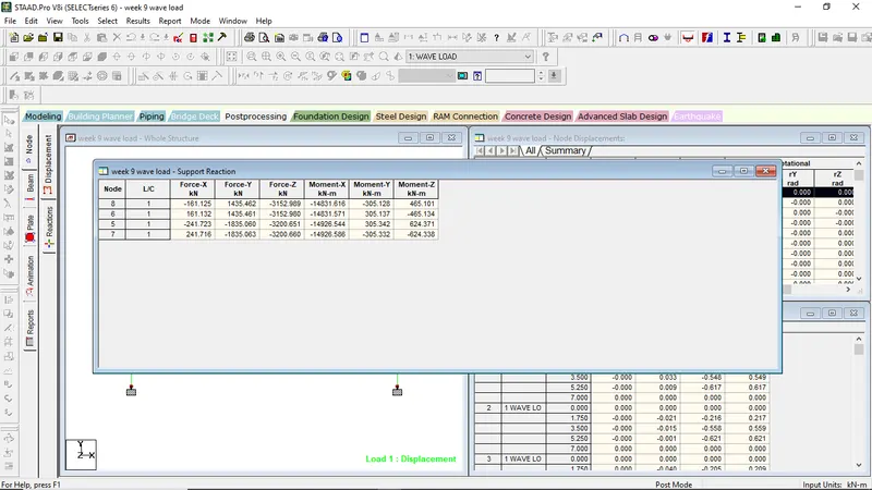
Values showing support condition for the structure
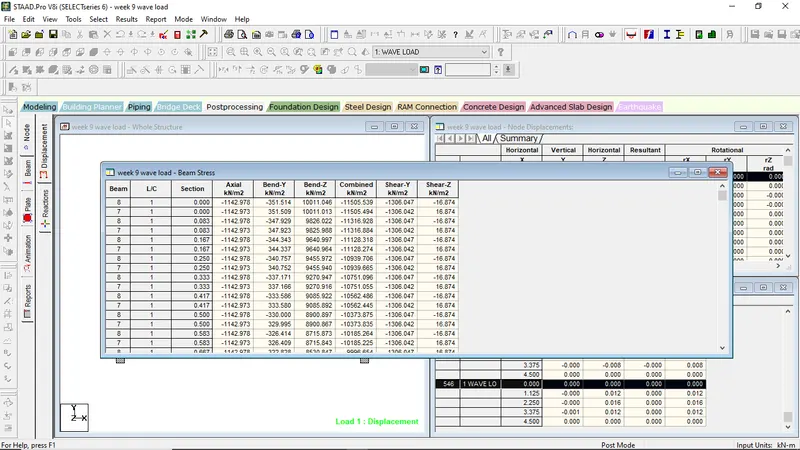
Values showing maximum bending stress if the model
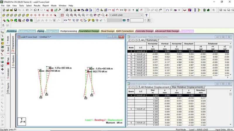
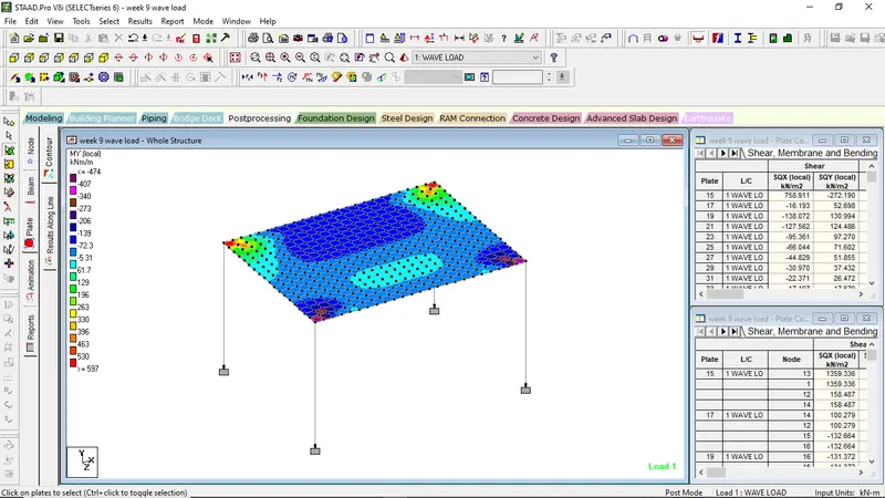
Plate Contour showing My local values on the plate on application of wave loads.