Week 9 Challenge
DESIGN AND ANALYSIS OF BRIDGE WITH WAVE LOADS
AIM
To Design and analyse a bridge with Wave load using STAAD Pro. Software.
INTRODUCTION
As per the given data and standard formulas the Wave load is being calculated manually.
η max = 3
Δ zh = 3 - (1.7/2)
= 2.15 m
Δ zv = η max - Elevation of bottom deck
= 3 - 1 = 2
Number of girders N = 3
F v = r x Δ zv x A v
= 5 x 2 x (9 x 1.7/2)
= 90 x 1.7/2
= 76.5 KN
F vmax = Cva x Fv
= 3 x 76.5 = 230 KN
F hmax = 1+Cr(N-1) x Cva + Fh = 2090 KN
PROCEDURE
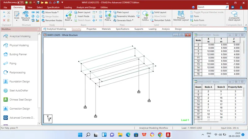
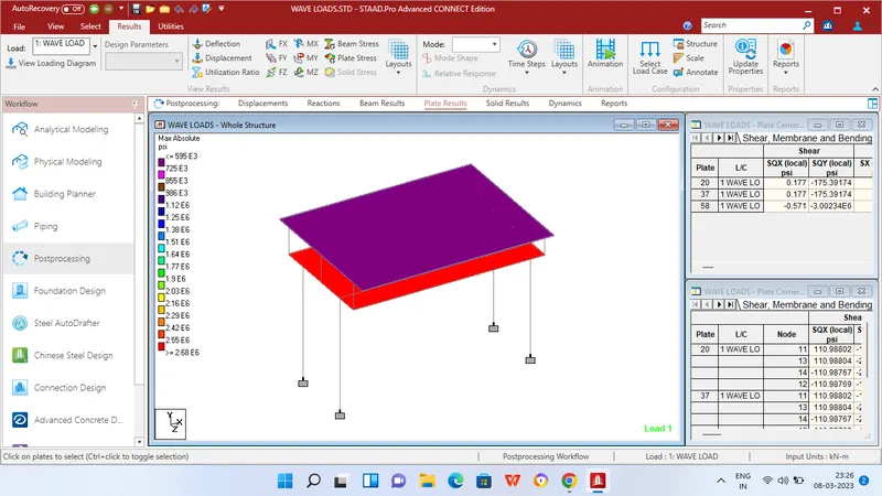
Step 1 - Create Nodes by entering the corresponding X/Y/Z values in the Node table for Creation of geometry for bridge structure with elements such as Piers,Rectangular Beams,I beams,Deck slab etc.,
Step 2 - After creating the nodes connect those nodes with add beam option and add plates with add plates option in Deck slab areas.
Step 3 - Then Click specification tab and click fixed support tab
Step 4 - After that in create support dialog box add fixed support for all the piers in the geometry using assign for selected nodes option.
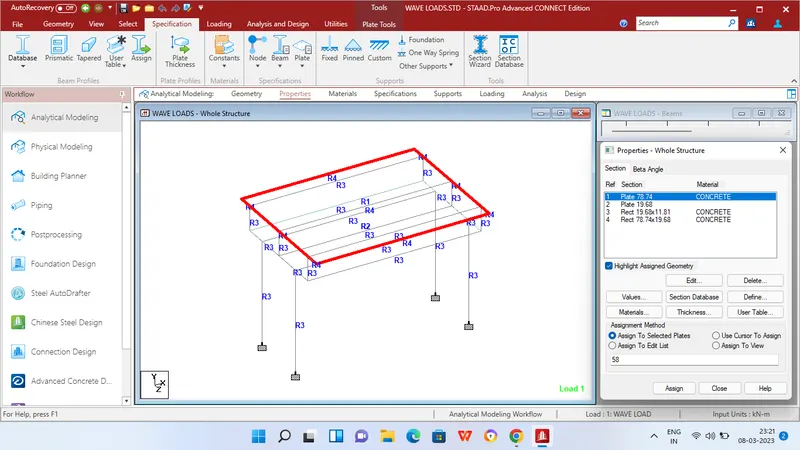
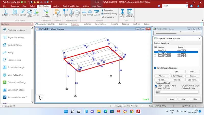
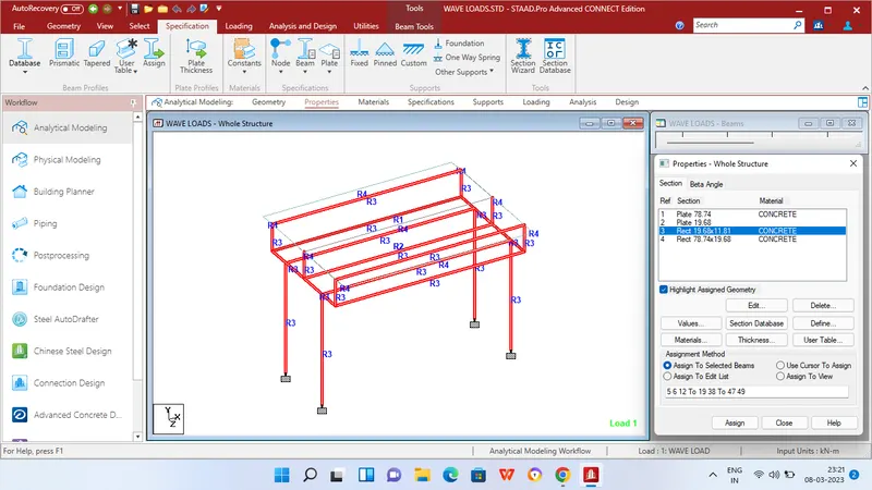
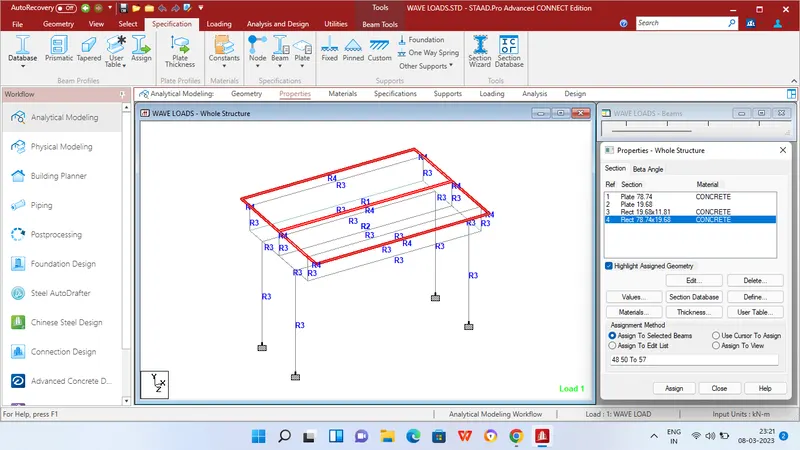
Step 5 - Then in Properties tab click Prismatic and add the Rectangle sections for beams and piers - 300mm x 500mm,Plates - 2m,500mm Thickness.
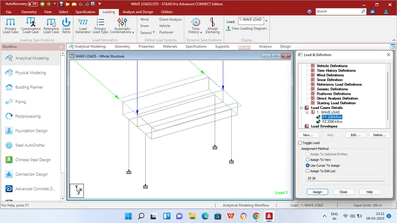
Step 6 - After adding the properties click Loading tab and add Wave load under Load cases.
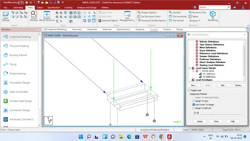
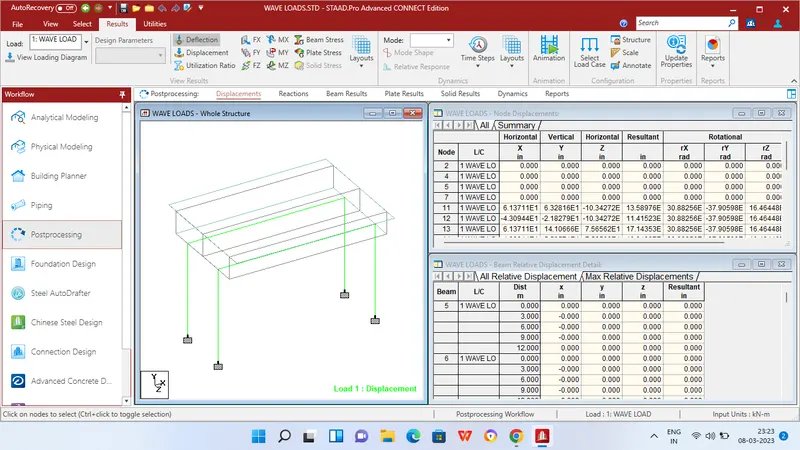
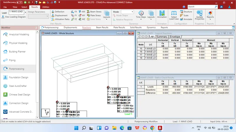
Step 7 - Then apply Nodal load of the calculated values of Maximum horizontal load = 2090 KN at Z direction and Maximum vertical load of 230 KN at Y direction.
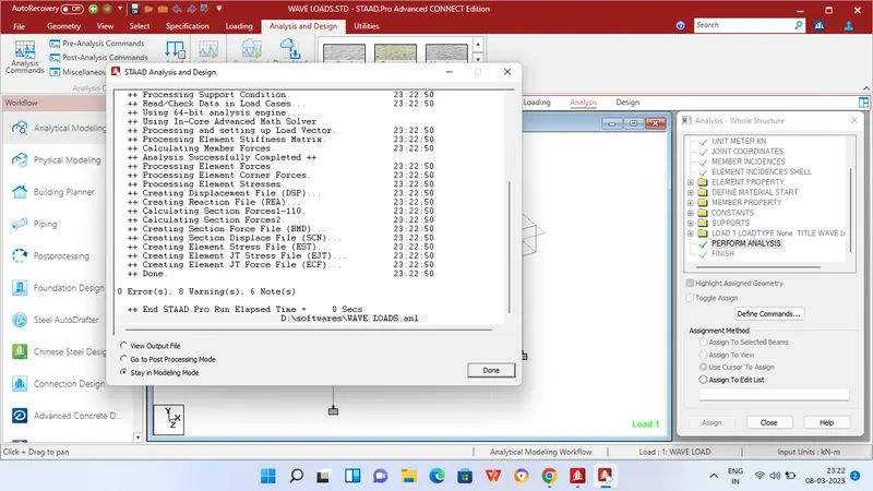
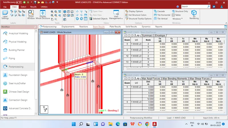
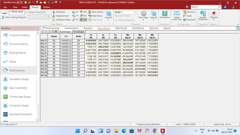
step 8 - Then in Analysis and design tab define commands for PERFORM ANALYSIS and click run analysis.
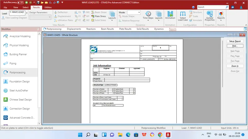
RESULTS