Week 1 Challenge
DESIGN AND ANALYSIS OF BOX GIRDER BRIDGE USING STAAD PRO.
AIM
To Analyse and design a box girder bridge using STAAD Pro. Software.
INTRODUCTION
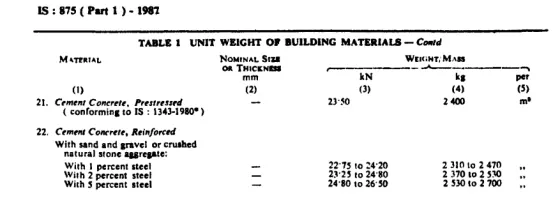
As per the given data to calculate the dead loads of the box girder bridge UNIT WEIGHT OF BUILDING MATERIALS/DEAD LOAD OF BUILDING MATERIALS AS PER IS 875(Part - 1) - 1987 is being considered for finding the dead loads of Deck slab and Box girder.The reference of the IS CODE is as below
PROCEDURE
- Manual Calculation
- Dimension and details of Deck slab and Box girder
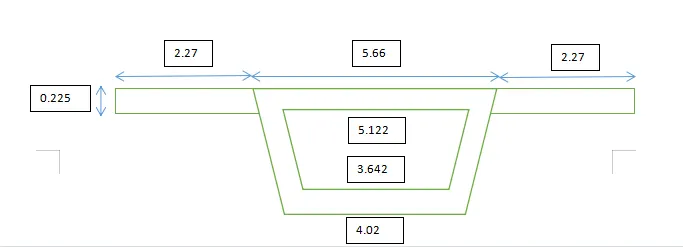
ii) Self weight of Deck slab = Width x Thickness x Unit weight of concrete
= 2 x 2.27 x 0.225 x 25 (Referred from IS CODE 875 - PART 1 Reference attached above)
Self weight of Deck slab = 25.53 KN
iii) Self weight of Box girder = Area x Unit weight of concrete
Area of box girder = Outer area - Inner area
Outer area = Area of triangle 1 + Area of rectangle + Area of triangle 2
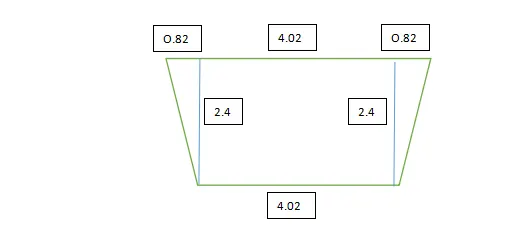
Area of triangle 1 and 2 = 2 x 1/2 x 0.82 x 2.4
= 1.968 sqm
Area of rectangle = 4.02 x 2.4
= 9.648 sqm
Outer area = 1.968 + 9.648
= 11.548 sqm
Inner area = Area of triangle 1 + Area of rectangle + Area of triangle 2
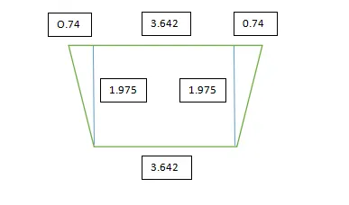
Area of triangle 1 and 2 = 2 x 1/2 x 0.74 x 1.975
= 1.462 sqm
Area of rectangle = 3.642 x 1.975
= 7.192 sqm
Outer area = 1.462 + 7.192
= 8.654 sqm
Total area of box girder = Outer area - Inner area
= 11.548 - 8.654
= 2.89 sqm
Self weight of box girder = Area x unit weight of concrete
= 2.89 x 25
Self weight of Box girder = 72.32 KN
Total self weight of the bridge = Self weight of Deck slab + Self weight of Box girder
= 25.53 + 72.32
TOTAL SELF WEIGHT OF THE BRIDGE = 97.85 KN
- Design of Box girder bridge in Staad pro.
Step 1 - Create Nodes by entering the corresponding X/Y/Z values in the Node table for Deck slab and box girder design.
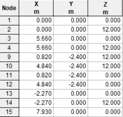
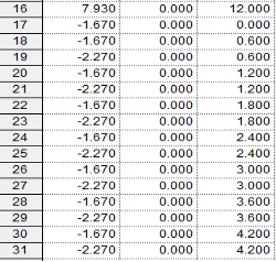
Step 2 - After creating the nodes connect those nodes with add beam option.
Step 3 - Then Click specification tab and click pinned support.
Step 4 - After that in create support dialog box add the required support with moment and forces assign to the four bottom corners of the box girder
Step 5 - After adding supports create required nodes in deck slab and box girder after that click Geometry tab and choose Add plates option
Step 6 - Then connect all 4 corners of the node with add plate option
Step 7 - Then in Properties tab click Prismatic and add the required property like Tapered I beam for corner Beams of the deck slab,Rectangular beams for box girder & cross beams,Plate thickness for all the plates in the geometry.
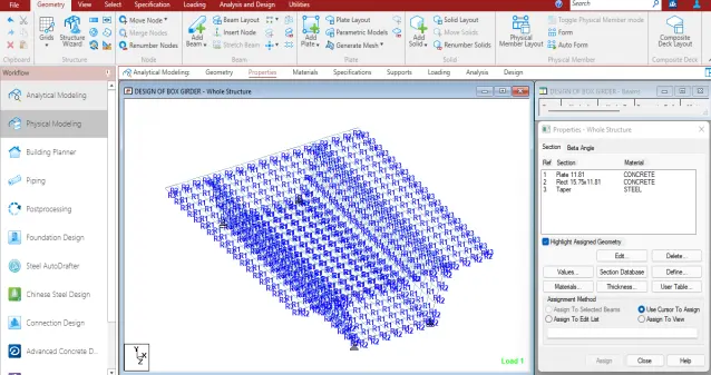
Step 8 - After adding the properties click Loading tab and add a primary load case as DEAD LOAD
Step 9 - Then click the Dead load tab and add the following Dead loads
- Self Weight Y direction - Applies to the whole geometry
- Uniformly distributed self weight 97.85 KN as obtained through manual calculation - Applies to corner I beams in Deck slab
- Super imposed dead load 5 KN/sqm standard for Footway - Applies to corner I beams in Deck slab
- Finishes Plate load 1.8 KN/sqm for Bitumen layer on the road - Applies to Deck slab
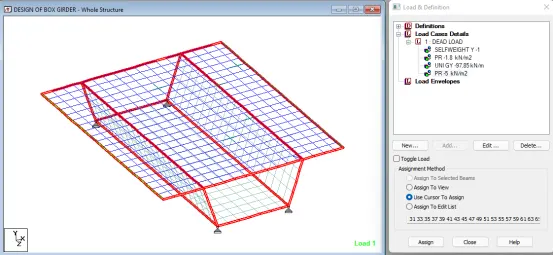
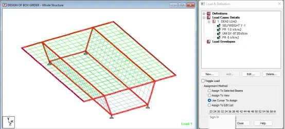
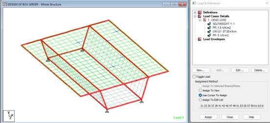
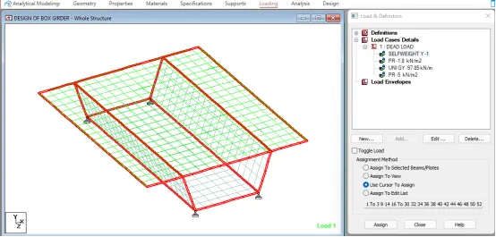
Step 10 - After applying the dead loads in analysis and design tab define commands for PERFORM ANALYSIS and click run analysis.
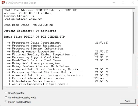
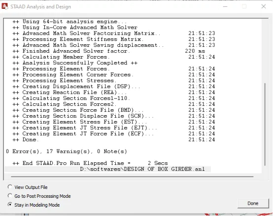
RESULTS
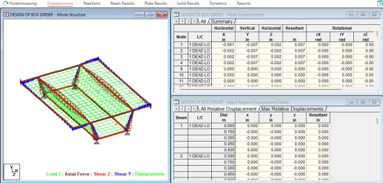
Axial Force displacement FX
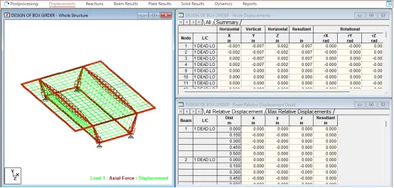
Axial Force - Shear Y displacement FX,FY
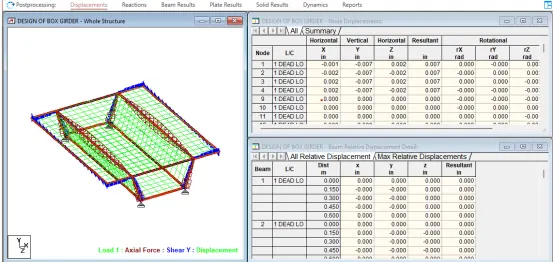
Axial Force - Shear Z - Shear Y displacement FX,FY,FZ
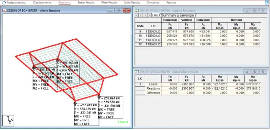
Reactions
Max Axial Force
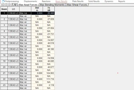
Plate results

REPORT
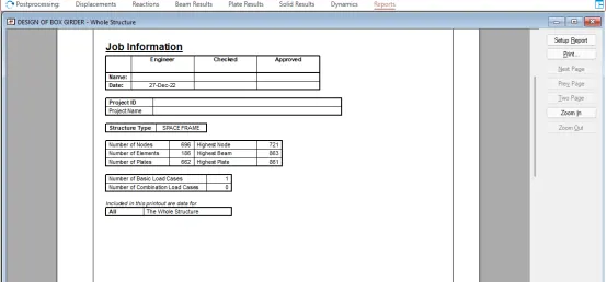
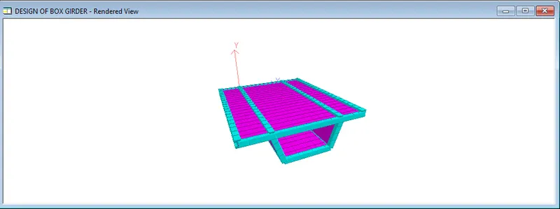
FINAL THREE DIMENSIONAL MODEL OF BOX GIRDER BRIDGE