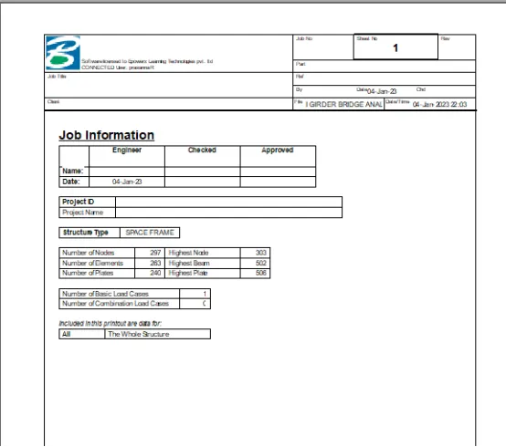
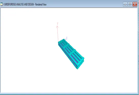
Week 2 Challenge
DESIGN AND ANALYSIS OF I GIRDER BRIDGE
AIM
To Analyse and design a I girder bridge using STAAD Pro. Software.
INTRODUCTION
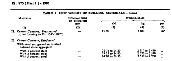
As per the given data to calculate the dead loads of the box girder bridge UNIT WEIGHT OF BUILDING MATERIALS/DEAD LOAD OF BUILDING MATERIALS AS PER IS 875(Part - 1) - 1987 is being considered for finding the dead loads of Deck slab and Box girder.The reference of the IS CODE is as below
PROCEDURE
Design of I girder bridge in Staad pro.
Step 1 - Create Nodes by entering the corresponding X/Y/Z values in the Node table for Deck slab,Main girder and cross girders for I girder design.
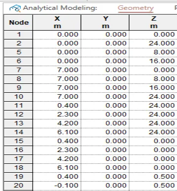
Step 2 - After creating the nodes connect those nodes with add beam option.
Step 3 - Then Click specification tab and click Fixed support.
Step 4 - After that in create support dialog box add the required support with moment and forces assign to the four bottom corners on both sides of the I girder
Step 5 - After adding supports create required nodes in deck slab and I girder after that click Geometry tab and choose Add plates option
Step 6 - Then connect all 4 corners of the node with add plate option
Step 7 - Then in Properties tab click Prismatic and add the required property like Tapered I beam for all girder beams as given in question, Beams of the deck slab,Plate thickness for all the plates in the geometry.
Step 8 - After adding the properties click Loading tab and in Definitions click Vehicle definition and click add
Step 9 - Then Define the moving load with width as 1.8m Load and distance as per standard
Step 10 - Then in Load case details add load generation and click ok.
Step 11 - Click the added load option from Generate load and enter the values of X,Y,Z Range,Increment,Maximum range in particular axis.
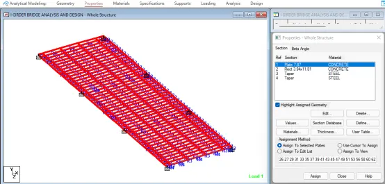
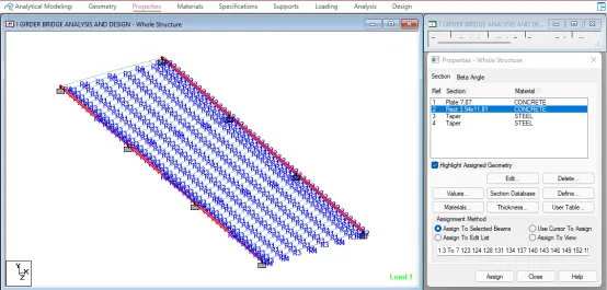
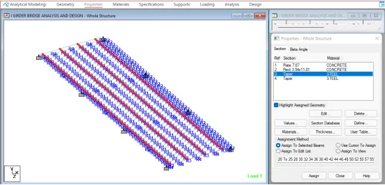
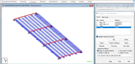
Step 12 - After applying the dead loads in analysis and design tab define commands for PERFORM ANALYSIS and click run analysis.
RESULTS
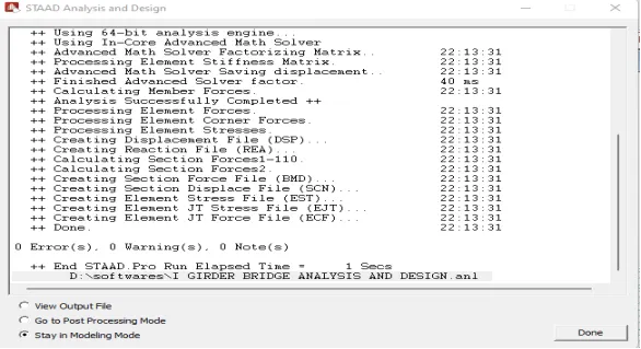
Run analysis
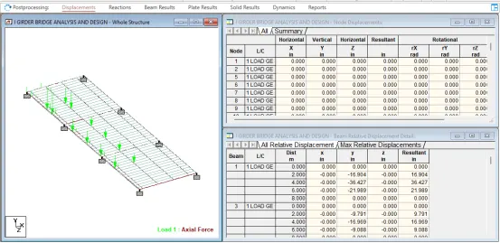
Loading diagram
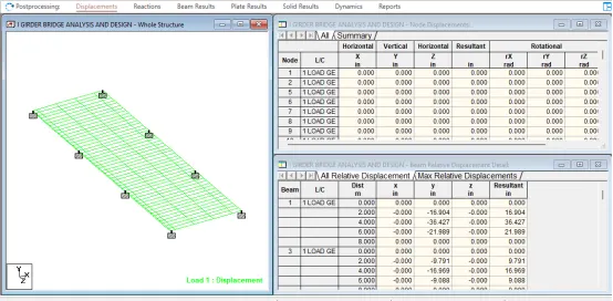
Displacements
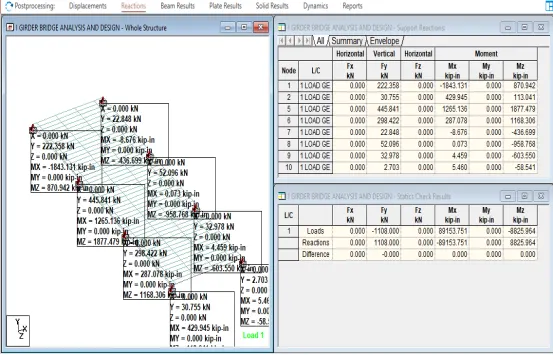
Reactions
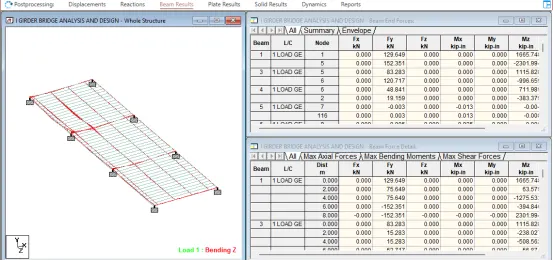
Beam Results
REPORT