Week 5 Challenge
DESIGN AND ANALYSIS OF BRIDGE WITH WIND LOADS
AIM
To Design and analyse a bridge with Wind loads using STAAD Pro. Software.
INTRODUCTION
As per the given data with reference of CODE OF PRACTICE FOR DESIGN LOADS AS PER IS 875(Part - 3) - 2015 and standard formulas the Wind force & Wind pressure is being calculated manually.
Wind force Vz = Vb x K1 x K2 x K3 x K4
Vb = 39 (For Mumbai as per given data)
K1 = 1.06 (From table 1 of IS 875 Part 3 )
K2 = 1.00 (For height 10m From IS 875 Part 3 Category 2 Table 2)
K3 = 1.00 (As per clause 6.3.3 From IS 875 Part 3 for upwind slope less than 3 Deg factor)
K4 = 1.30(When the location is within 60 km radius of ocean the cyclone factor is taken in account)
so,Vz = 39 x 1.06 x 1.00 x 1.00 x 1.30 = 53.74 N/m2
Pz = 0.6Vz2 = 0.6 x (53.74)^2 = 1.73 KN/m2
PROCEDURE
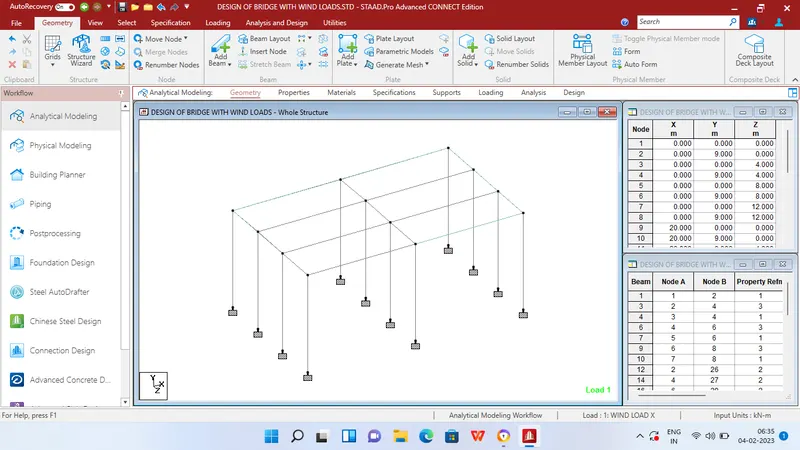
Step 1 - Create Nodes by entering the corresponding X/Y/Z values in the Node table for Creation of geometry for bridge structure with elements such as Piers,Beams,Deck slab etc.,
Step 2 - After creating the nodes connect those nodes with add beam option.
Step 3 - Then Click specification tab and click fixed support tab
Step 4 - After that in create support dialog box add fixed support for all the piers in the geometry using assign for selected nodes option.
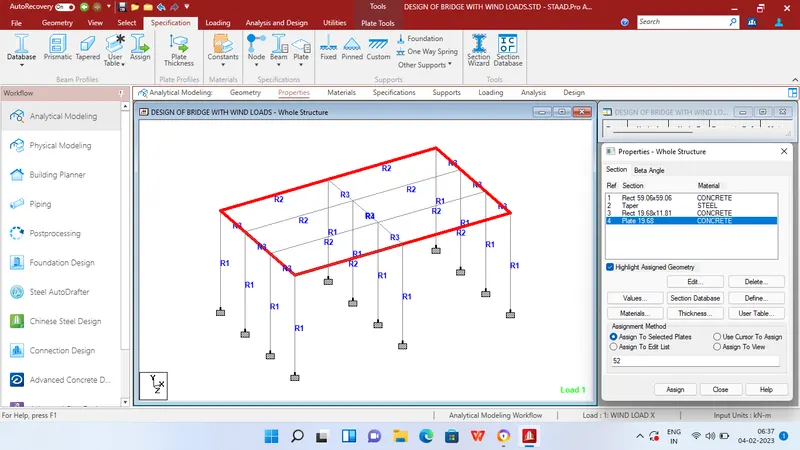
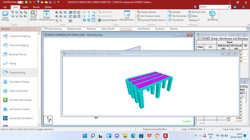
Step 5 - After adding supports choose Add plates option and provide deck slab
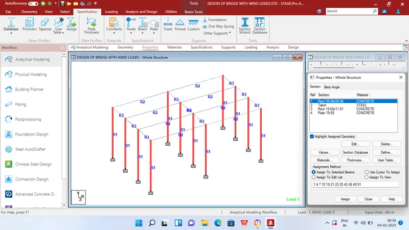
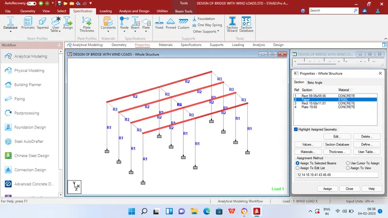
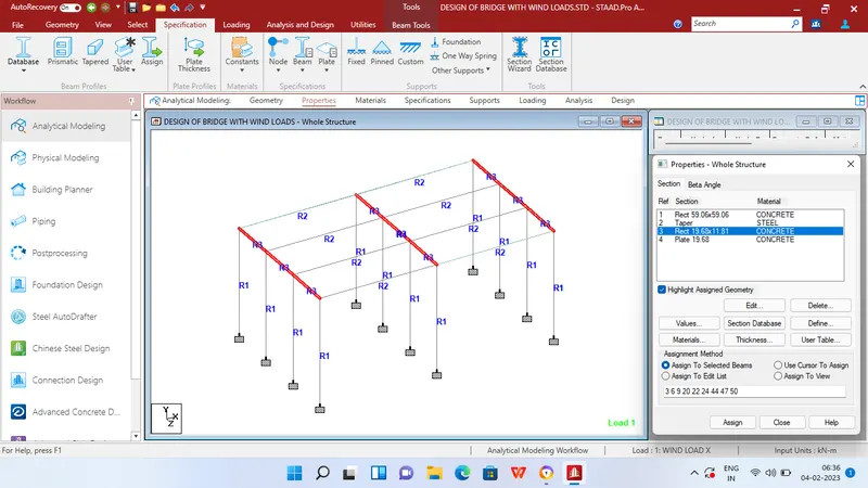
Step 6 - Then in Properties tab click Prismatic and add the required property like Thickness of plate for 0.5m for deck slab,I beam for main girder,Rectangular beam for cross girder and for pier.
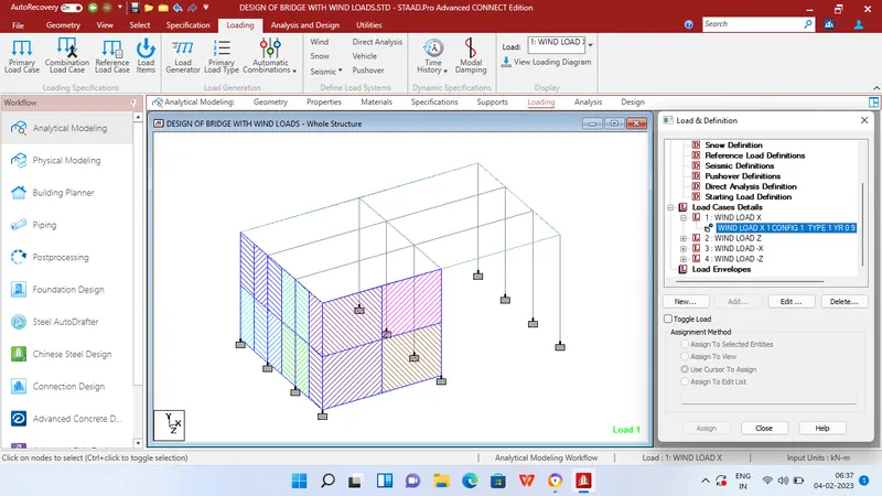
Step 7 - After adding the properties click Loading tab Definitions Define Wind load .
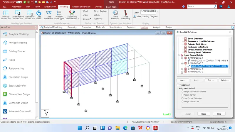
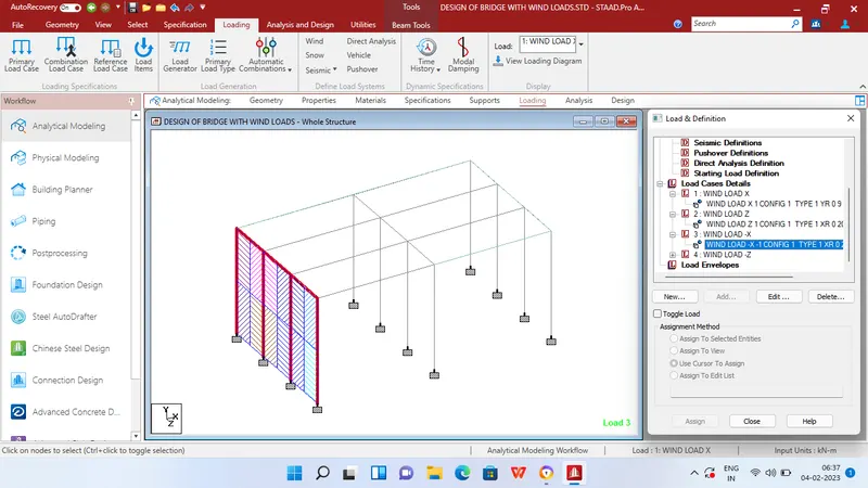
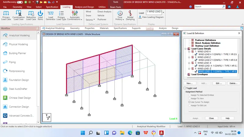
Step 8 - Then in Load case option add 4 Load cases named Load on +X,+Z,-X,-Z Then apply 4 load cases on the appopriate sides of the bridge with load value as 1.73 KN/m2 as per manual calcuation above.
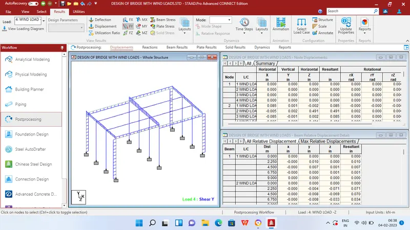
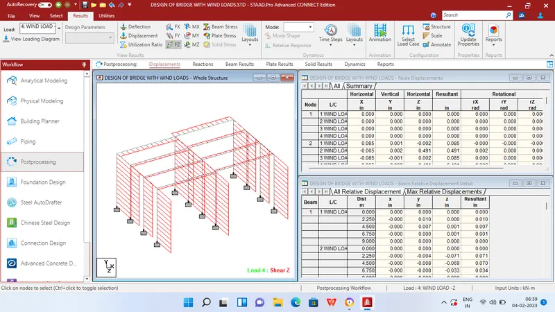
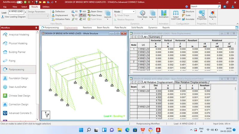
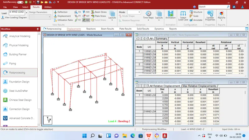
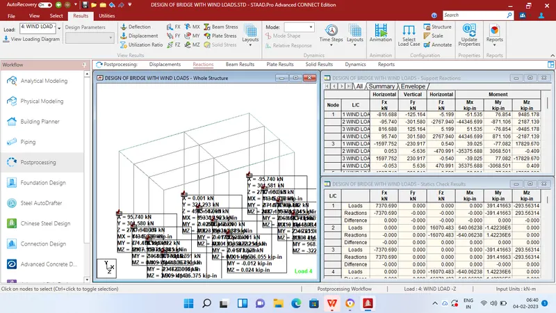
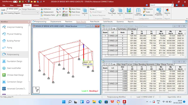
Step 9 - After applying the loads in analysis and design tab define commands for PERFORM ANALYSIS and click run analysis.
RESULTS