Week 9 Challenge
Analysis & design of Typical Steel Frame structure using STAAD. Pro
Q1. Design of dual slope (pitched) roof frame
Ans:
Aim: Design of dual slope pitched roof frame to draw the bending moment shear
Procedure:
Step 1:Open the staad and create the model structure of file and open it
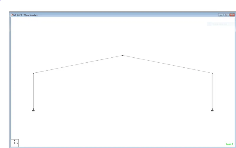
Step 2: Design and assign the nodes and beams as per given data
Step 3: Assign properties of structure such as tapered section and beta angles for columns and cretae and design the support to columns and internal hinge
Step 4:Add loading such as load case details as per given DD and LL
Dead load -Wt of roofing sheet +Wt of purlins +teritary members=(5+25)=30Kg/m^2
Live load = 75Kg/m^2
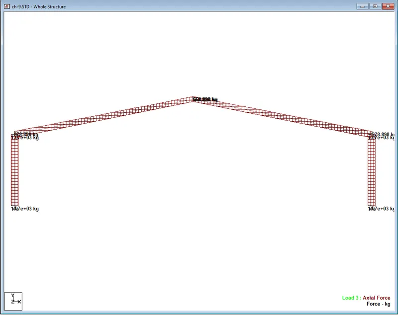
For the given frame for load combination D.L +L.L the axial laod diagram
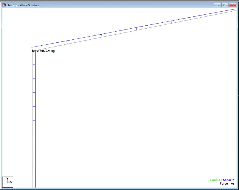
Shear force diagram
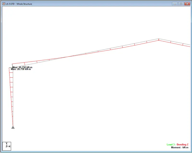
Bending moment diagram
2. Draw Bending Moment diagram for following Frame using STAAD.Pro
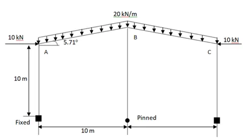
Figure 1)
Given:
Supports are fixed and pinned
Angles of slope=5.71degrees
Width of frame= 20m
Height of end column=10m
Height of mid column =10tan 5.71-1
=11
Loading UDL =20kN/m
Point load = 10kN
Procedure:
Create frame model and assign properties to beams and columns
Assign the loading to section of member and run the analysis
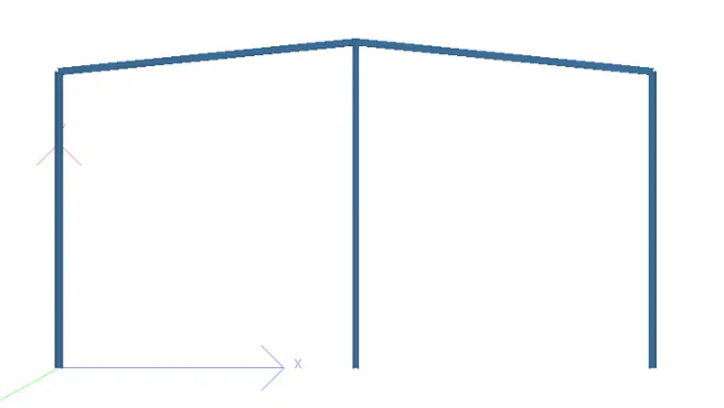
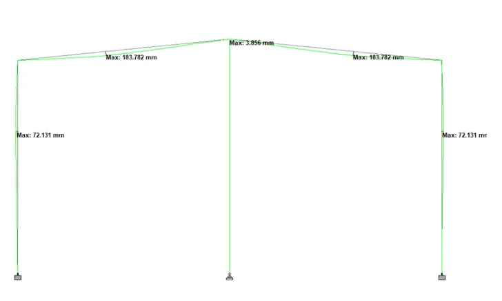
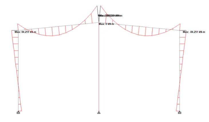
Figure 2)
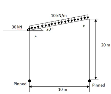
Given:
Supports are pinned
Angles of slope=20 degrees
Width of frame= 10m
Height of end column=20m
Height of mid column =10tan20=3.64m
Height of mid column =20-3.64=16.36m
Loading UDL =10kN/m
Point load = 30kN
Procedure:
Create frame model and assign properties to beams and columns
Assign the loading to section of member and run the analysis
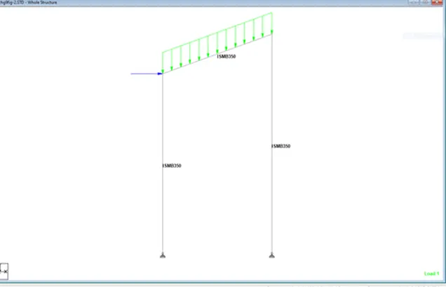
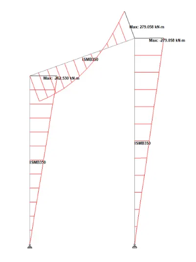
Figure 3)
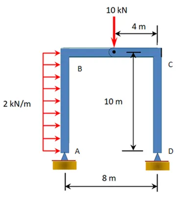
Given:
Supports are hinged
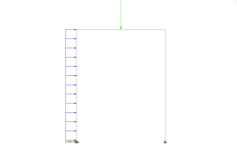
Width of frame= 8 m
Height of end column=10m
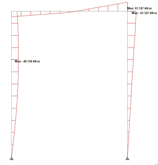
Loading UDL =20kN/m
Point load = 10kN
Procedure:
Create frame model and assign properties to beams and columns
Assign the loading to section of member and run the analysis
3. Deflection of a frame, present result from STAAD.Pro
Determine the lateral deflection at point A & Vertical deflection at mid section of beam between B & C in fig 1
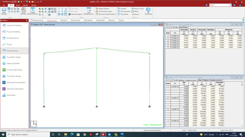
Lateral displacement at A is 0.101mm at A the vertical displacement 3.856 at B the vertical displacement 1.431
ii)Determine the lateral deflection at point A & Vertical deflection at mid section of beam between A & B from Figure 2
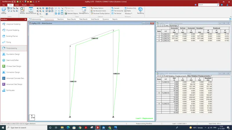
Lateral displacement at A is 1.377 mm at A the vertical displacement 0.049 at B the vertical displacement 1.436
iii)Determine the lateral deflection at point A & point B from Figure 3
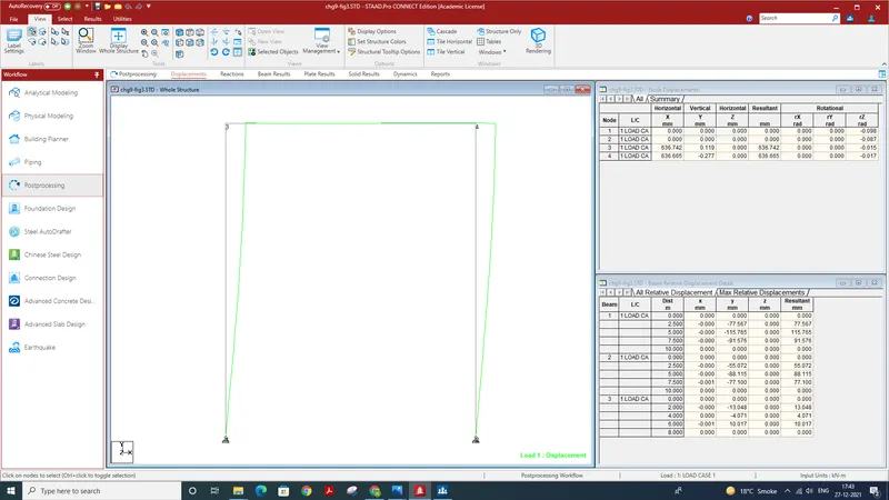
Lateral displacement at A is 636.742 mm at B the vertical displacement 0.277 downwards