3D Creation of Celing, Roof, Architectural plan, Structural plan, Sectional view, Elevation view and Camera specific view for a house plan using REVIT
Q1) Aim: To create a ceiling on the first floor
Step 1: Open week 3 Revit project file and select first floor
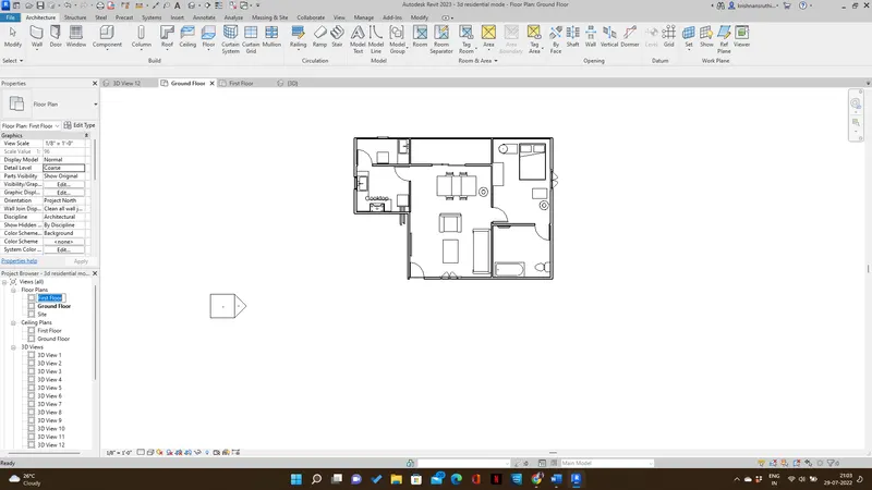
Step 2: Go to the architecture tab and select ceiling
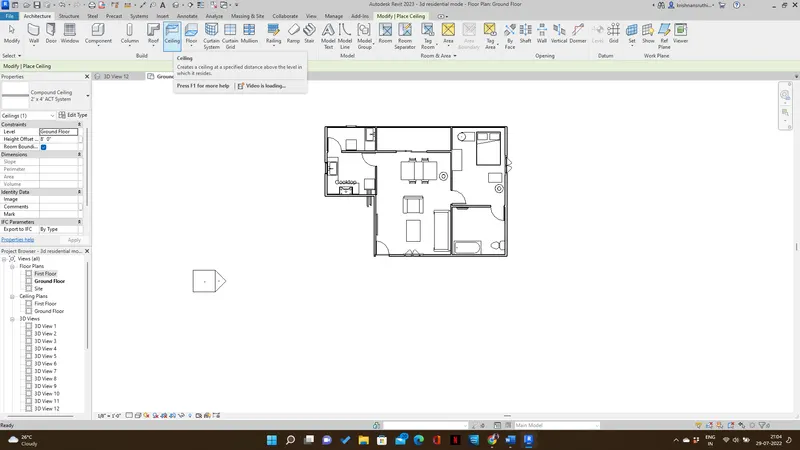
Step 3: Select sketch ceiling
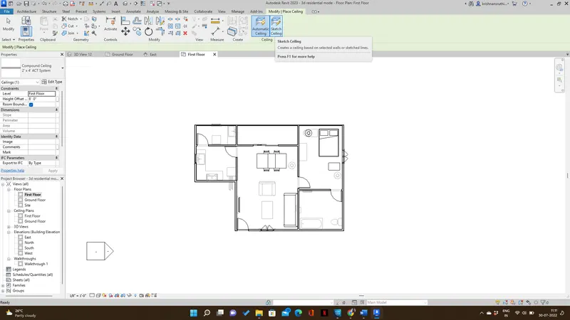
Step 4: A ribbon tab will appear >select pick line
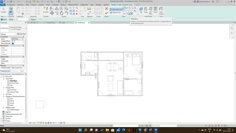
Step 5: Select all the outer sides of the wall >ok
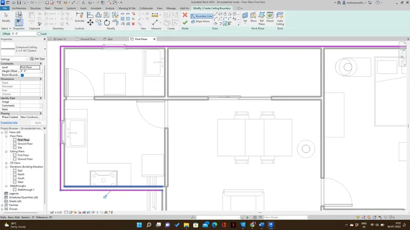
Step 6: Select all the inner sides of the wall >ok
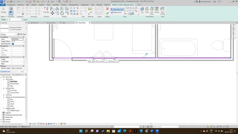
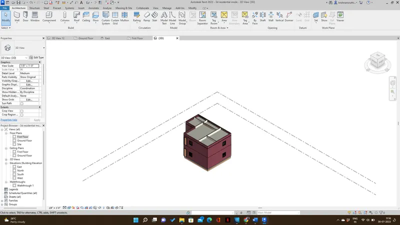
Result: Ceiling created successfully
Q2)Aim: To create a roof and change its slope as 100
Step 1: Go to the first-floor level
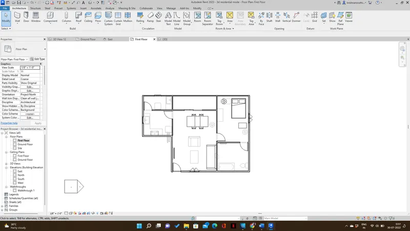
Step 2: Go to the architecture tab and select roof
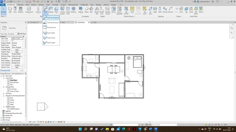
Step 3: A ribbon tab will appear >select pick line
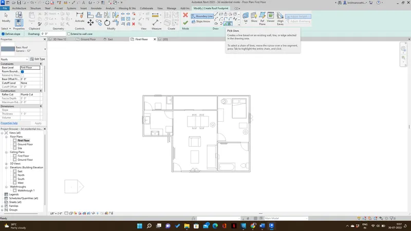
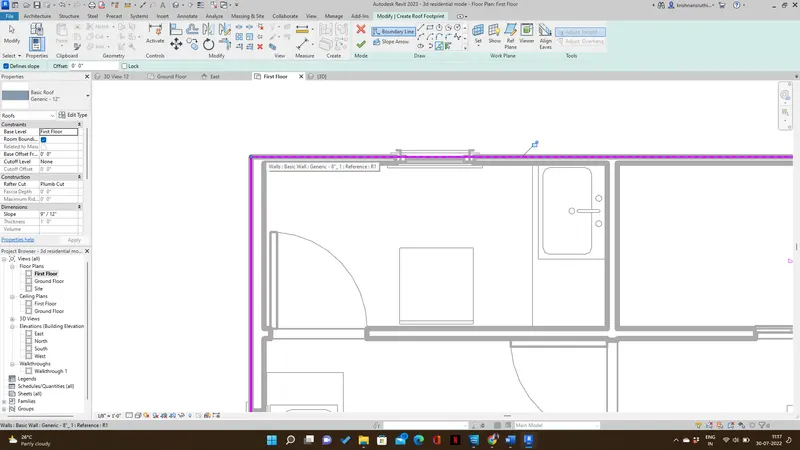
Step 4: Select all the corners of the outer sides of the wall >ok
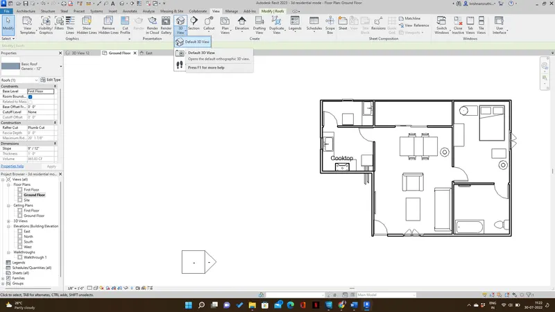
Step 5:Go to view tab >3D view
Step 6:Type UN >ribbon tab will appear
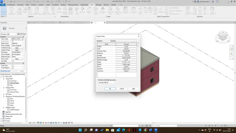
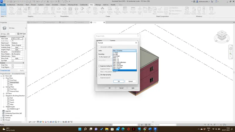
Step 7: Select slope and change the unit to degree>ok
Step 8: Click the roof and change the slope in the property browser as 100
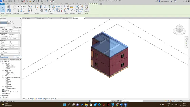
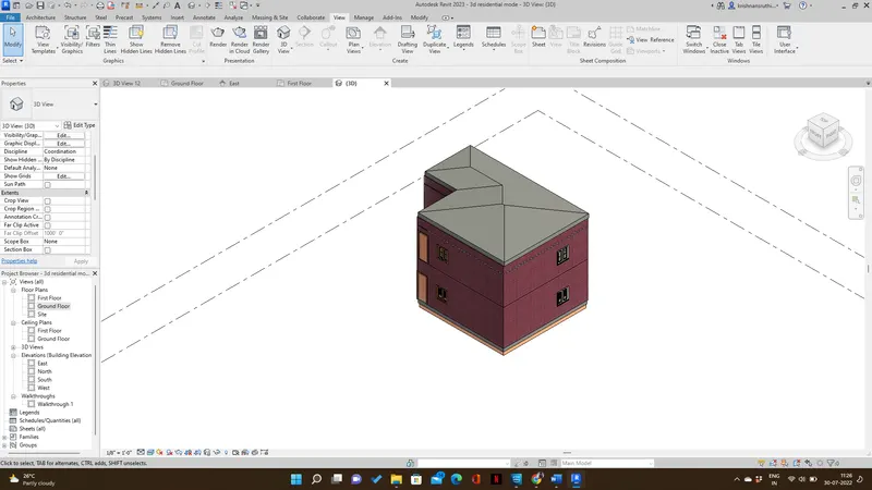
Result: Successfully created Roof and change the slope
Q3)Aim: To create plan views for ground level and first-floor level including all walls, floors, and components, and separate them to the architecture plans and structural plans
A)
Step 1: Go to the ground floor and click the view tab and select plan view
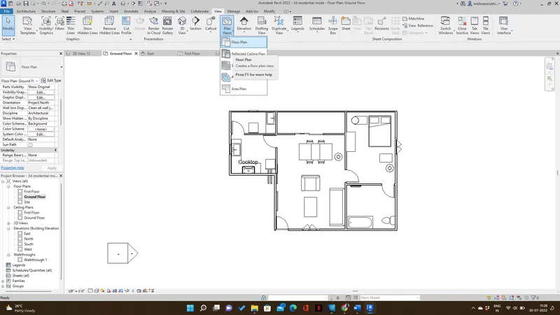
Step 2:Select floor plan
Step 3: A dialog box will appear >select edit type >ok
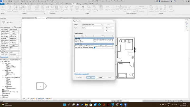
Step 4: Go to the first floor and click the view tab and select plan view
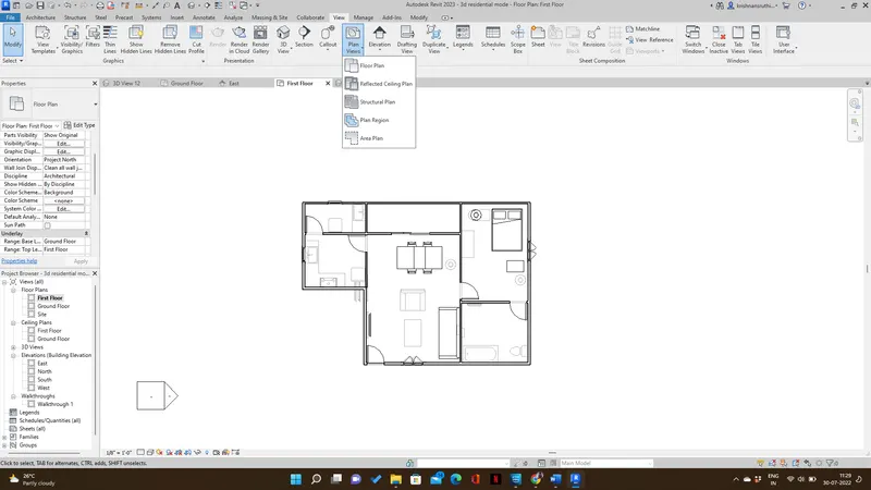
Step 5:Select floor plan
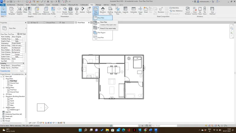
Step 6: A dialog box will appear >select edit type >ok
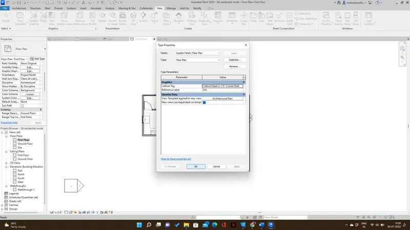
B)
Step 1: Go to the view tab and select plan view
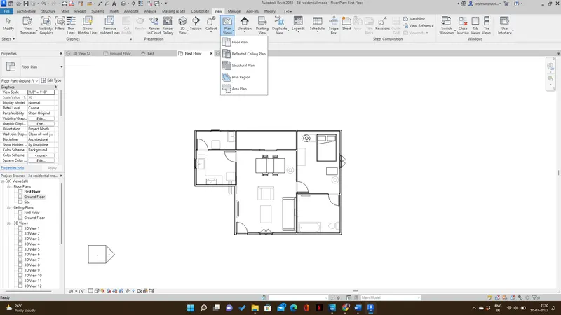
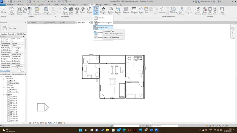
Step 2:Select structural plan
Step 3: A dialog box will appear >select ground floor >ok
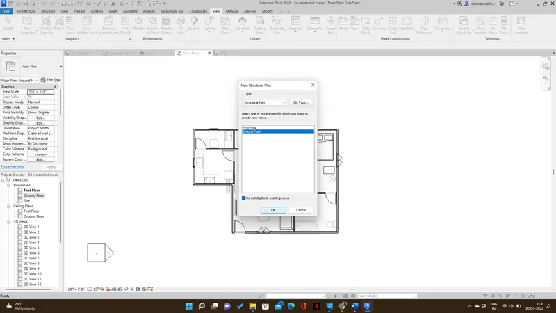
Step 4: Go to the view tab and select plan view
Step 5:Select structural plan
Step 6: A dialog box will appear >select first floor >ok
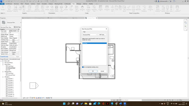
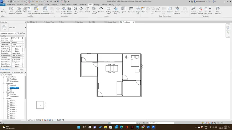
RESULT: Successfully created architectural and structural plan for ground floor and first floor
Q4)Aim: To dimension all the walls and floors concerning longitudinal and transverse grids created in the project file
A)
Step 1: Open the Revit file in the architecture plan
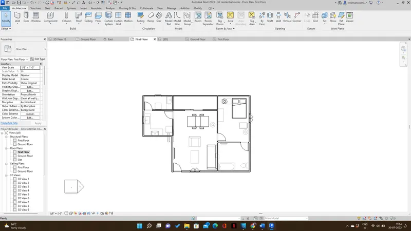
Step 2: Go to annotate tab and select linear
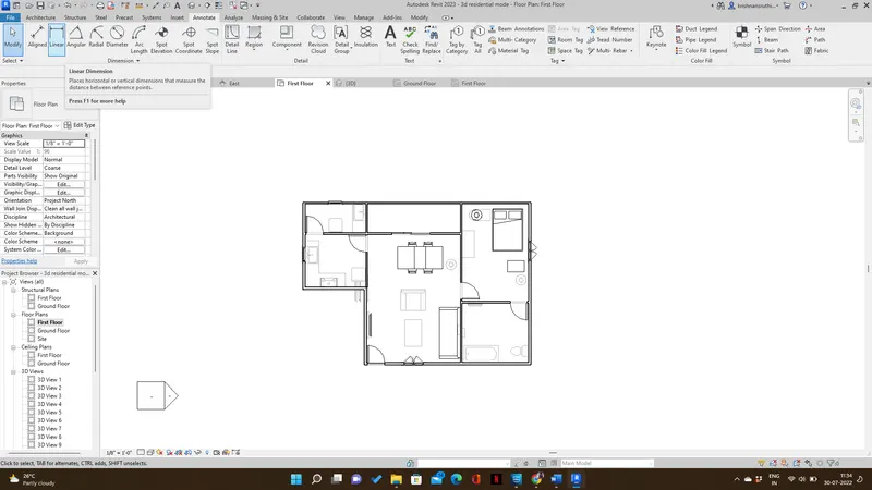
Step 3: click the edges of the wall and add dimensions
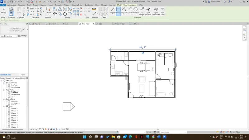
B)
Step 4: Go to the structural plan
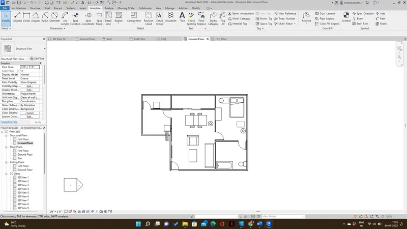
Step 5: Go to annotate tab and select linear
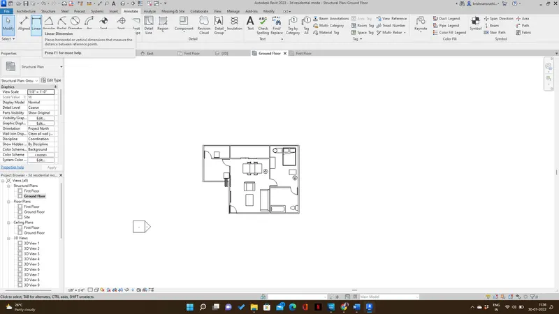
Step 6: click the edges of the wall and add dimensions
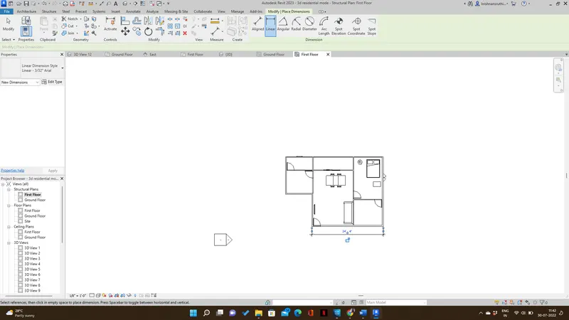
Result: Successfully annotated
Q5)Aim: To create a sheet template and add views to the sheet
Step 1: Go to file
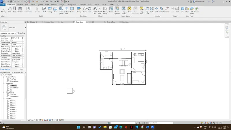
Step 2: Go to the view tab and select sheet
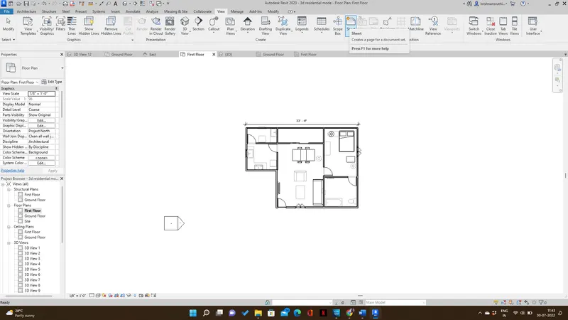
Step 3: A ribbon tab will appear >select sheet size >ok
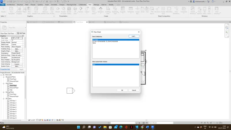
Step 4: Sheet will be created
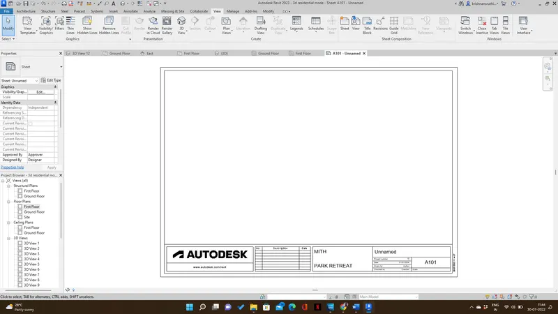
Step 5:Double click the name in the sheet and rename it
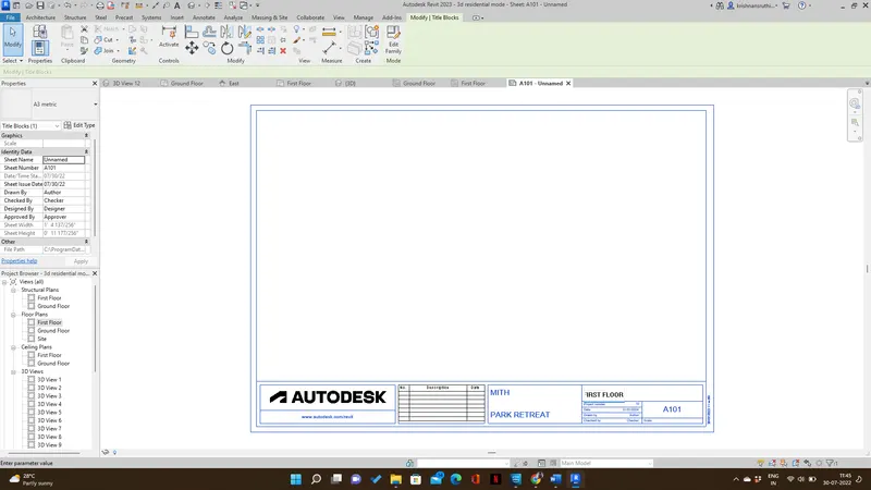
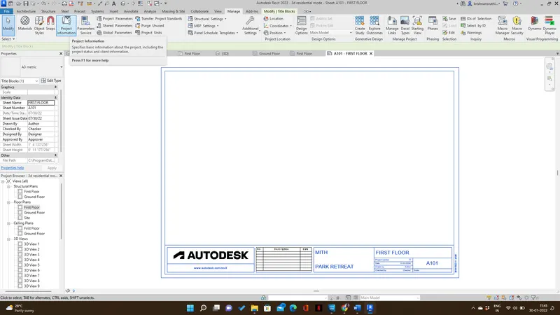
Or
Go to the manage tab and select project information and edit >ok
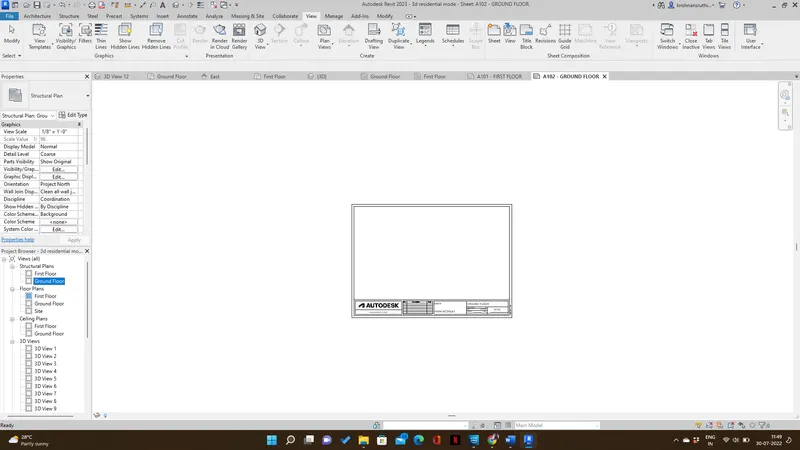
Step 6:Select ground floor plan from the architectural and structural plan in the project browser
Step 7: Drag it to the sheet >enter
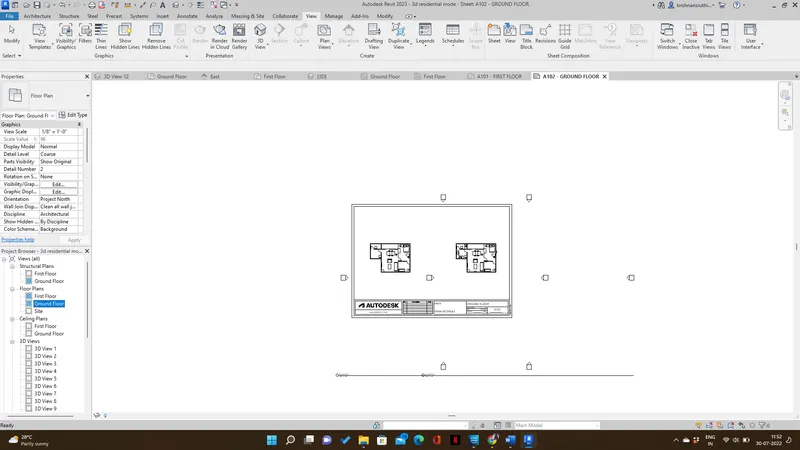
Step 7:Select first floor plan from the architectural and structural plan in the project browser
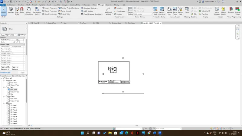
Step 8: Drag it to the sheet >enter
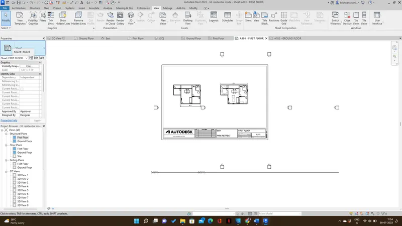
Result: Successfully created sheet and add views
Q6)Aim: To create the elevation view using the elevation tab for four views
Step 1: Go to the view tab and click elevation>elevation
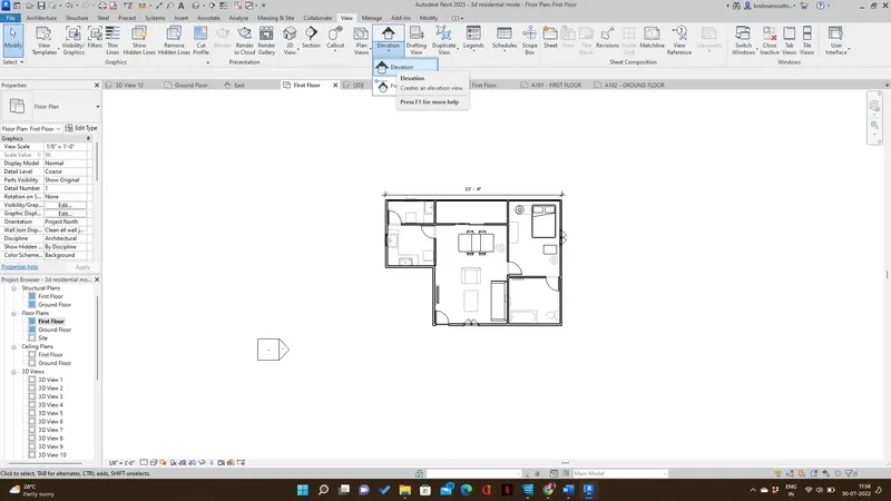
Step 2:Place the elevation toward east, west, north, and south in the floor plan
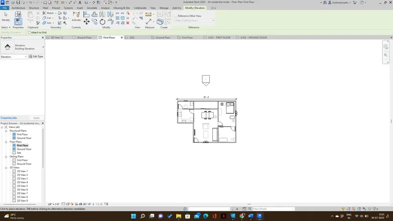
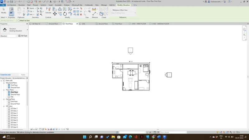
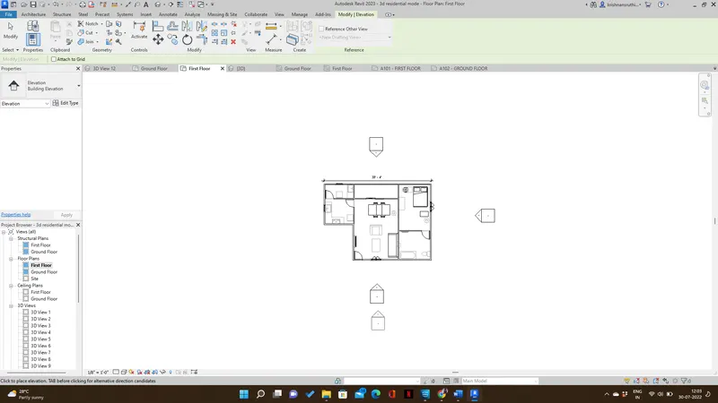
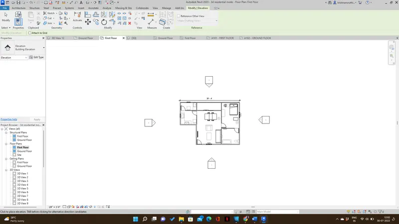
Step 3: Rename it as east, west, north, and south respectively
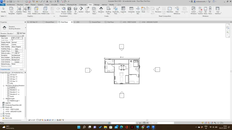
Result: Successfully created elevation view for four views
Q7)Aim: To create section cut using view tab either longitudinally or transverse
Step 1: Go to the ground floor plan
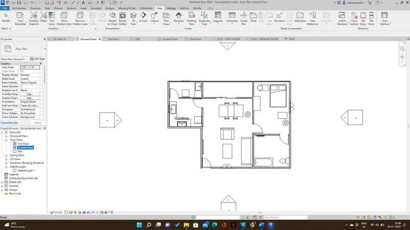
Step 2: Click the view tab and select the section
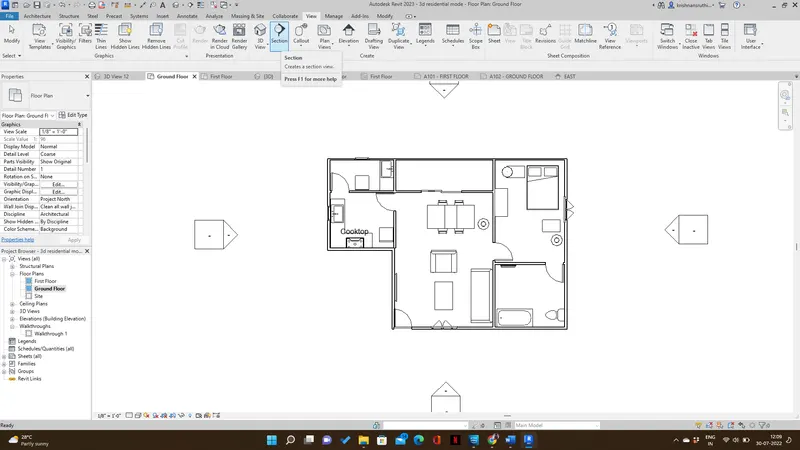
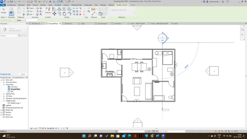
Step 3: Cut the room longitudinally
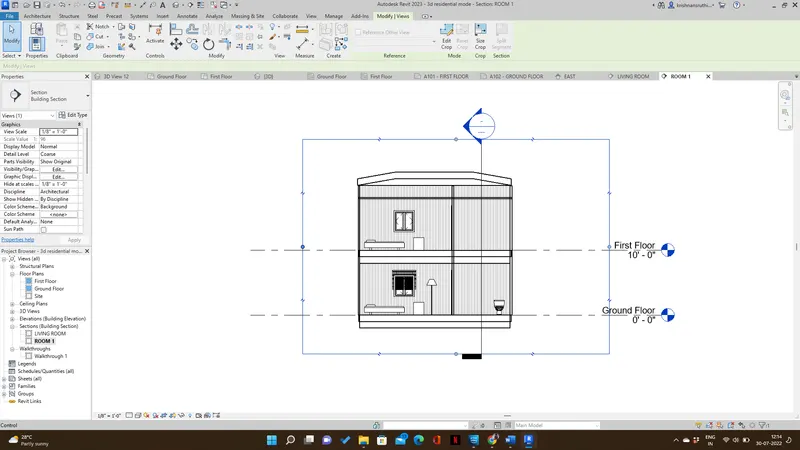
Step 4: Go to the project browser > right click and rename it
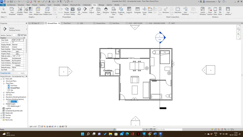
Step 5: Click the view tab and select the section
Step 6: Cut the room transversely
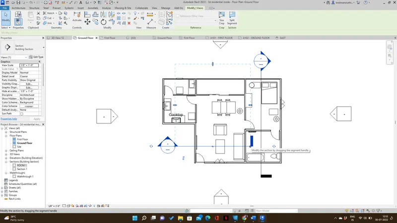
Step 7: Go to the project browser > right click and rename it
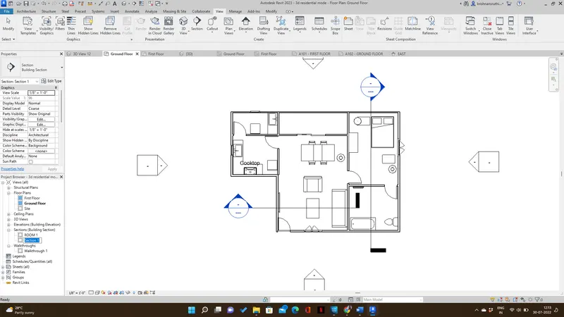
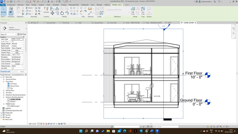
RESULT: Successfully created sections
Q8)Aim: To classify all the views from the property browser
Step 1: Go to the project browser
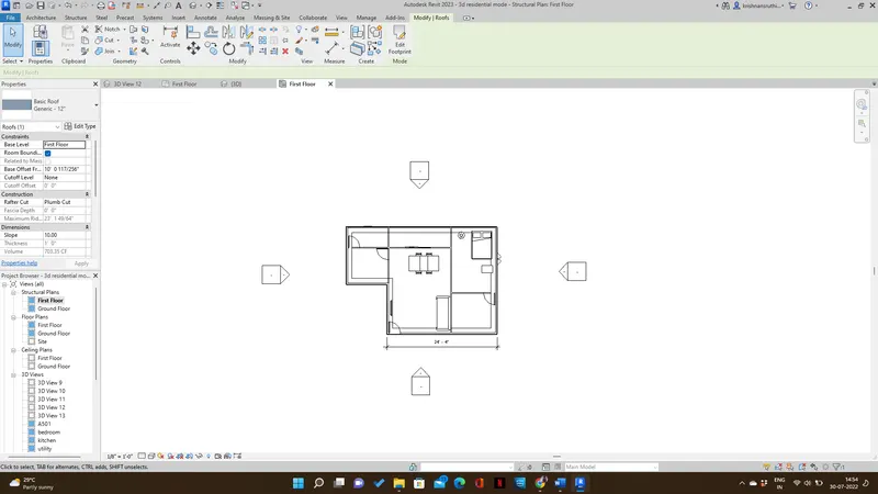
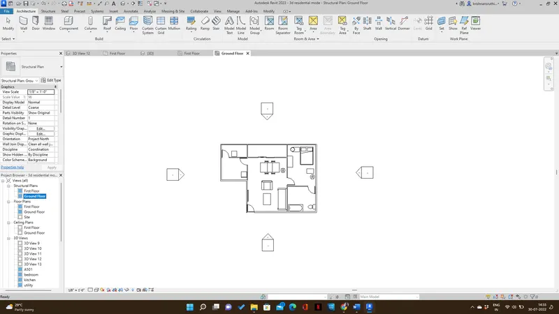
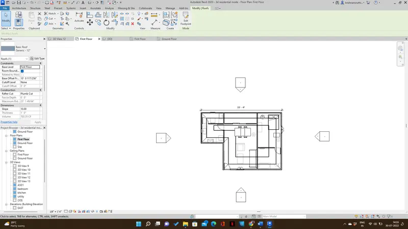
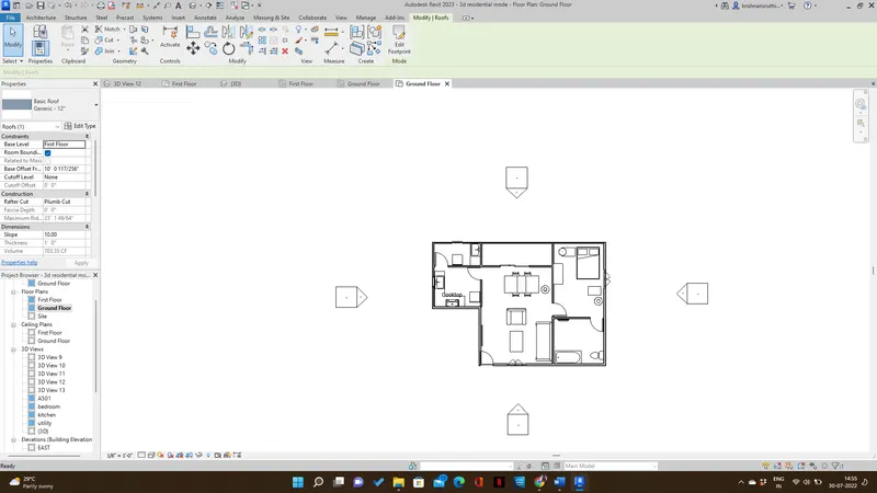
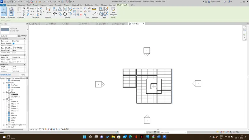
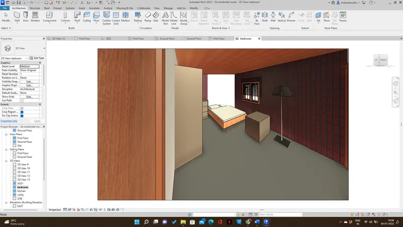
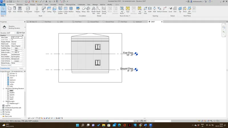
Result: Successfully classify views
Q9)Aim: To create sheets
Step 1: Go to the view tab and select sheet
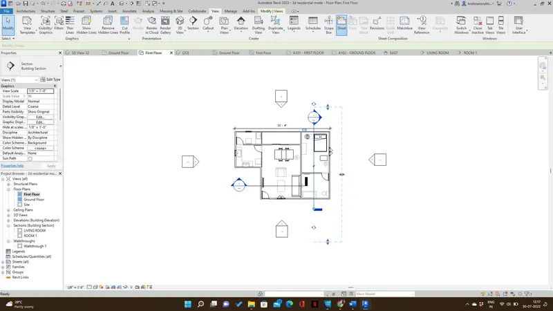
Step 2: Go to the project browser and drag the view to the sheet and rename it as follow:
a. A 101- Ground Floor Architecture Plan
b. A 102- First Floor Architecture Plan
c. A 103- Roof Plan
d. S 101- Ground Floor Structural Plan
e. S 102- First Floor Structural Plan
f. S 103- Roof Framing Plan
g. A-201- North-South Elevations
h. A-202- East-West Elevations
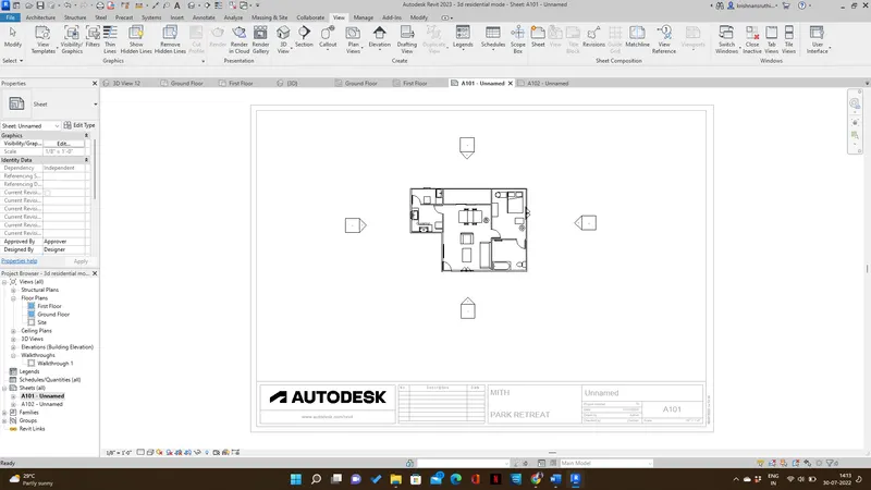
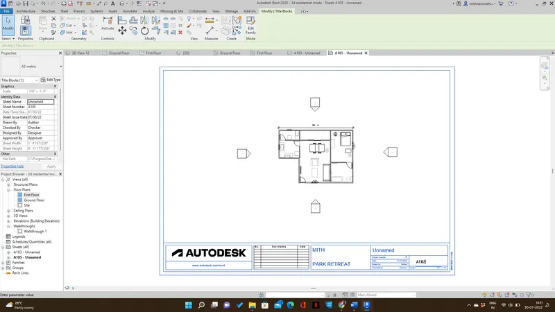
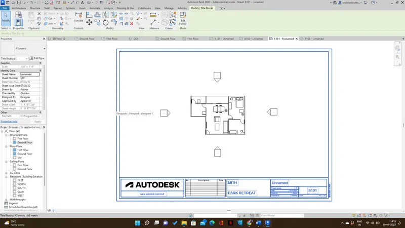
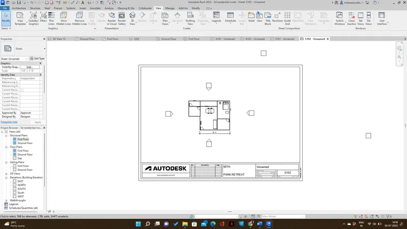
Result: Successfully created sheets and place the views to the sheet and rename it as given
Q10)Aim: To create a camera view or 3D view in each room and to create the sheet separately for each camera view and rename it
Step 1: Go to view tab >3D view>camera
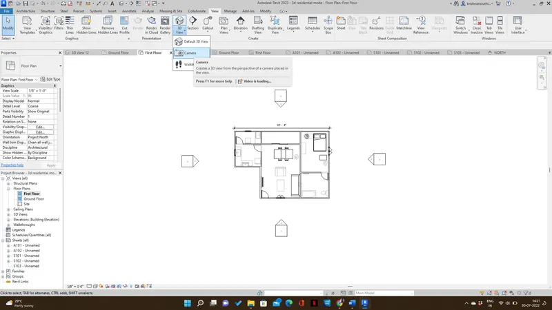
Step 2: Place the camera >enter
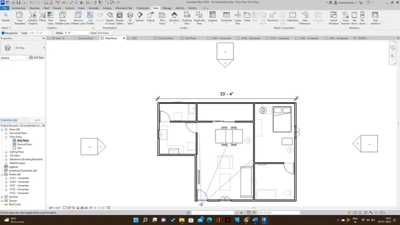
Step 3: Rename it in the project browser
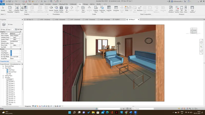
Step 4: Go to the view tab and select sheet
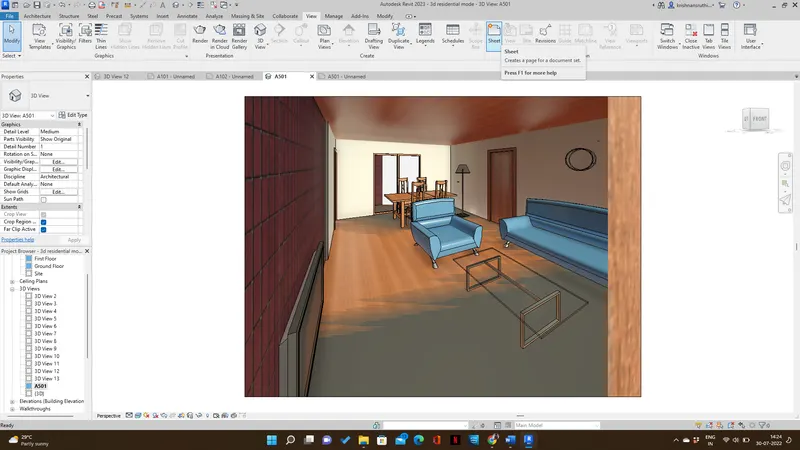
Step 5: A ribbon tab will appear >select sheet size >ok
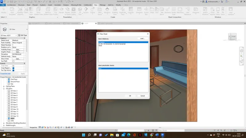
Step 6: Sheet will be created
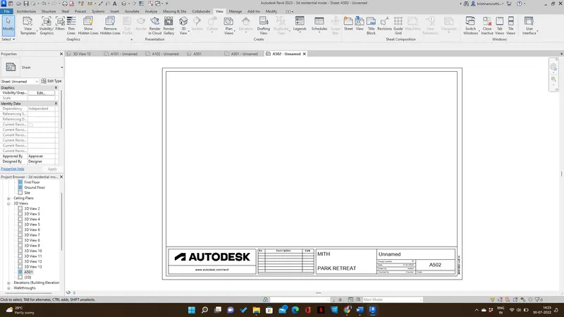
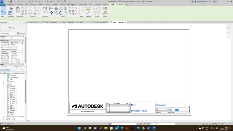
Step 7:Double click the name in the sheet and rename it
Step 8: Drag the camera views to the sheet >enter
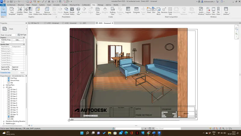
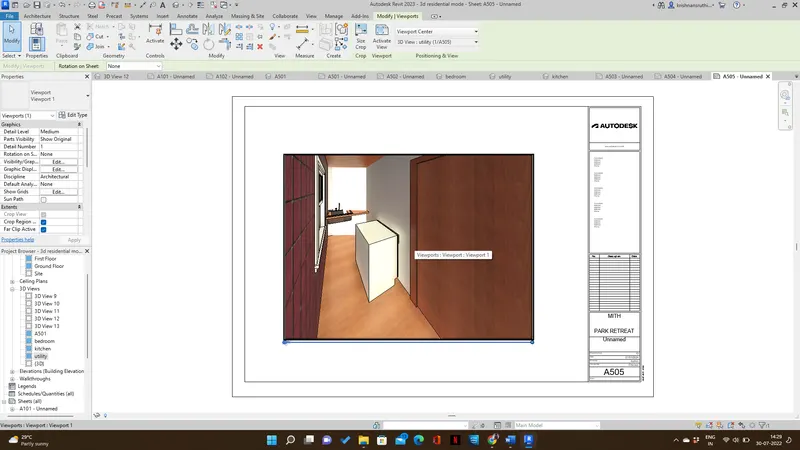
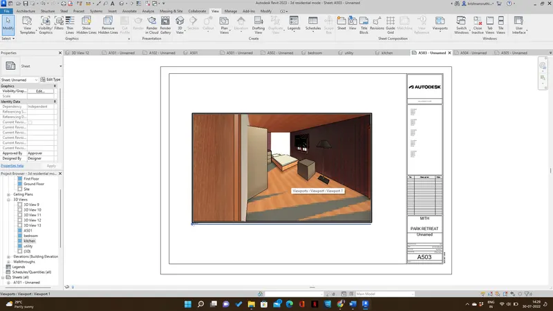
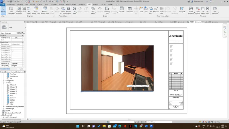
RESULT: Successfully created camera view and create the sheet separately for each camera view and rename it