Introduction to REVIT concepts
INTRODUCTION TO REVIT CONCEPTS
Q1)AIM: To create a new project and name the project
INTRODUCTION:
- Rivet is a building information modeling tool that is an error-free drawing software. It helps Architects, structural engineers, MEP engineers, etc.
- To create a new project open architectural or structural templates and give the project name and save
- Name the project is an essential part of a work.
PROCEDURE:
Step 1: Open REVIT software
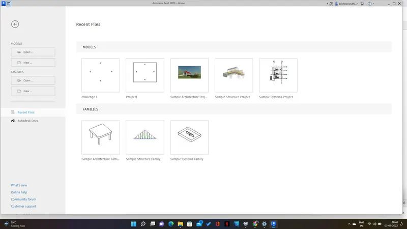
Step 2: Click new from the left side tab
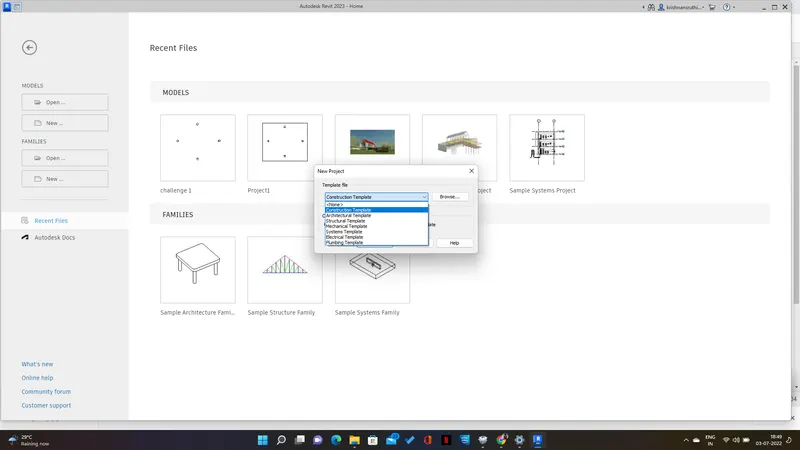
Select the construction template from the template tab that is visible on the screen and click ok
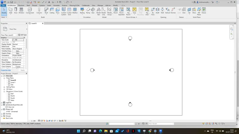
Step 3: New project floor plan appeared
Open the file toolbar and click on the save as option
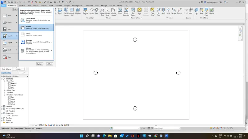
Step 4: Select the folder and save the project with the project file name with extension .rvt
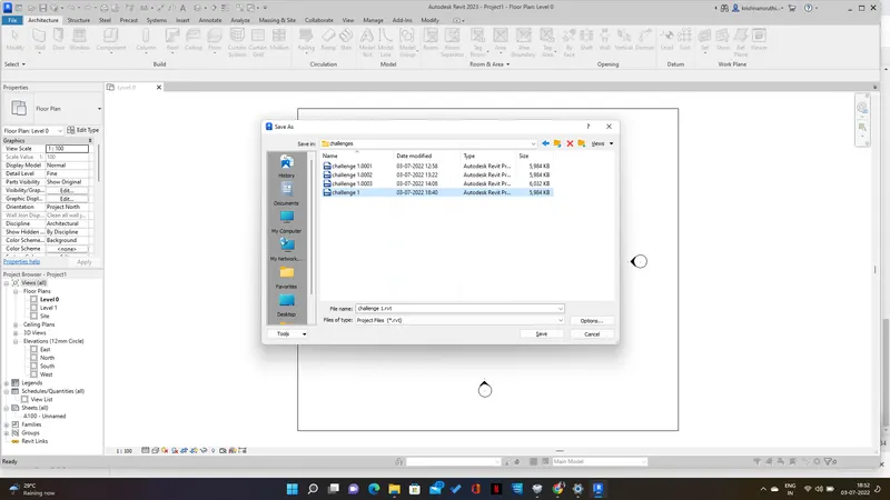
Result: Create a new project with the new file name 'Challenge 1'
Q2)AIM: Save a new project file and also want to close and open using icons.
PROCEDURE:
Step 1:Open the file toolbar and the click save option
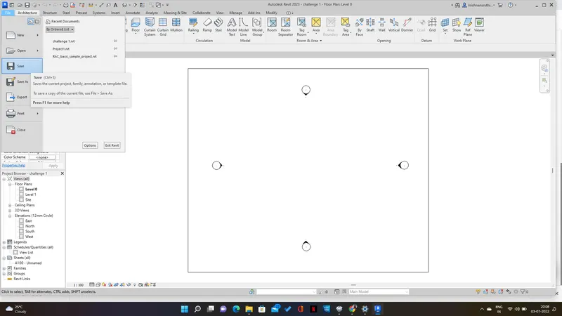
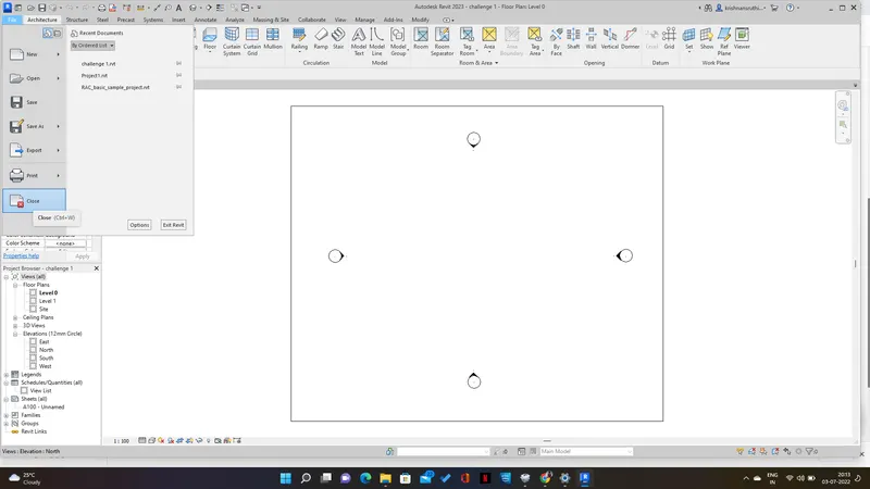
STEP 2:Open the file toolbar and close the window
Step 3: Open the project from the recent files
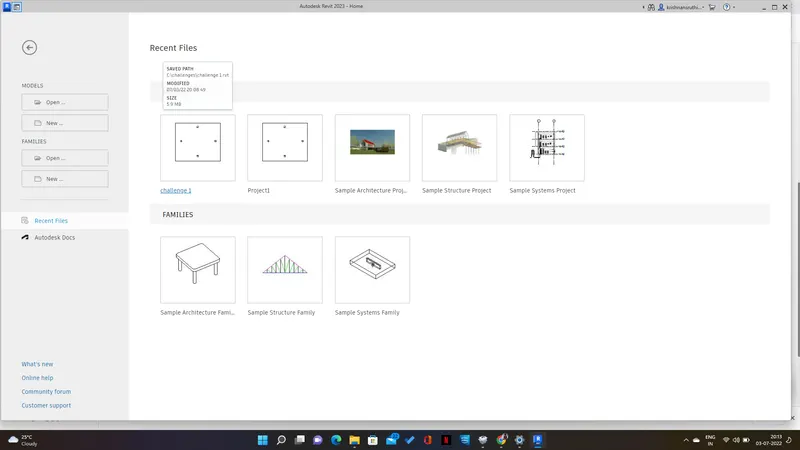
Result: New project saved & opened and close the project using icons
Q3) AIM: To draw a rectangular layout of the wall of about 40'*35'
INTRODUCTION: There are different types of walls that are in the architecture toolbar for different disciplines like architecture, structure, etc.
PROCEDURE
Step 1:From the toolbar select the architectural tab and click on the wall
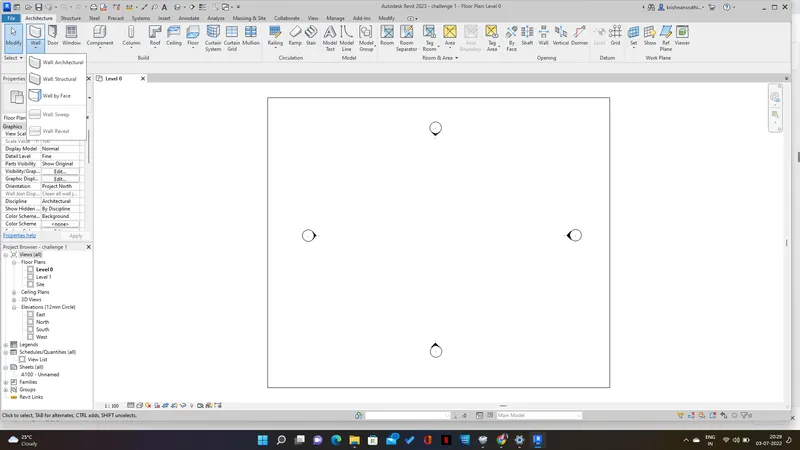
Step 2:selct the line option from the tab
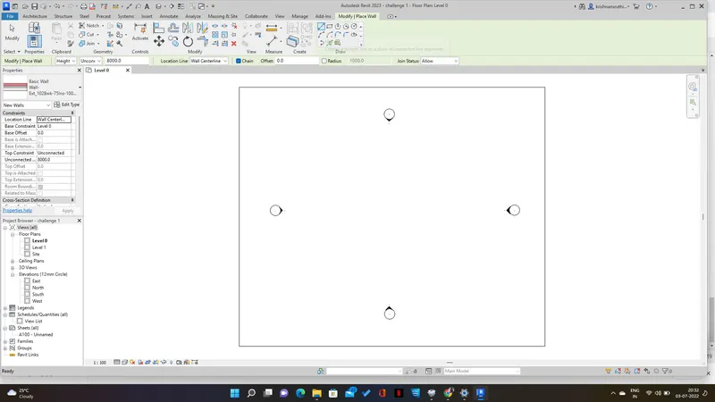
Step 3: Draw the rectangular layout with size 40'*35'
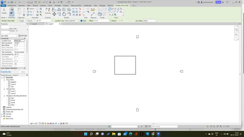
RESULT: Create a rectangular layout with dimensions 40'*35'
Q4) Aim: Dimensioning the layout created using annotate icon
Introduction: Dimensioning each object is a necessary thing for that in rivet there is an annotate toolbar.
Using the linear or aligned option in the toolbar we can annotate the layout
Procedure
Step1: Select annotate from the menu toolbar
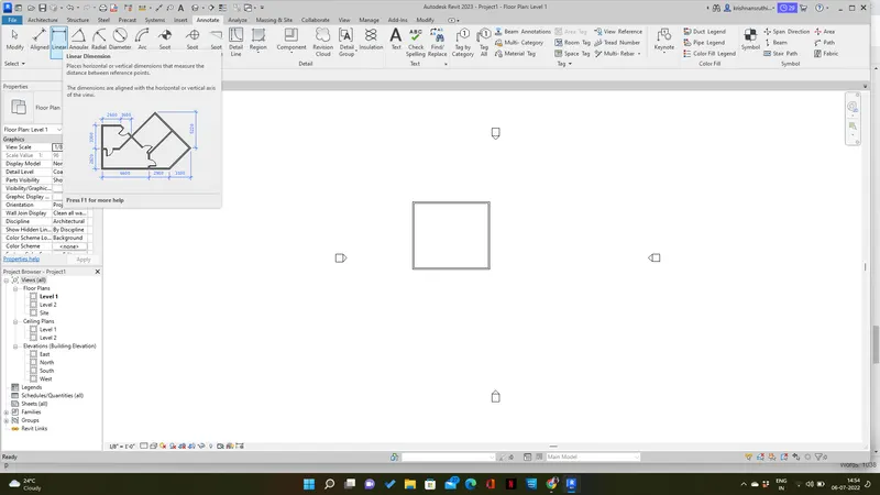
Step2:Dimensionong the layout using an aligned or linear option
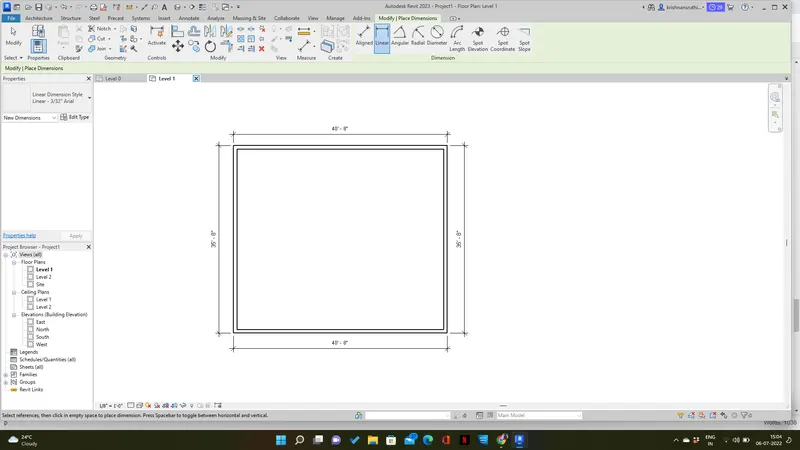
Result: Successfully dimensioning the rectangular layout with size 40'*35'
Q5)Aim: Switch the type of each wall using the property browser
- Introduction: Different types of walls can be used in the rectangular layout.
- We can select the wall types from the property browser.
Procedure:
Step 1: Select the default 3D view from the top menu bar and click the 3D view
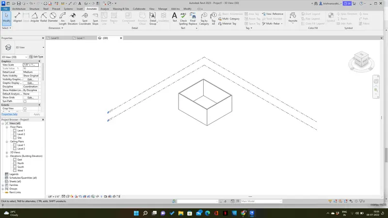
Step 2:From the rectangular layout select each wall and change the types using the property browser on the left side
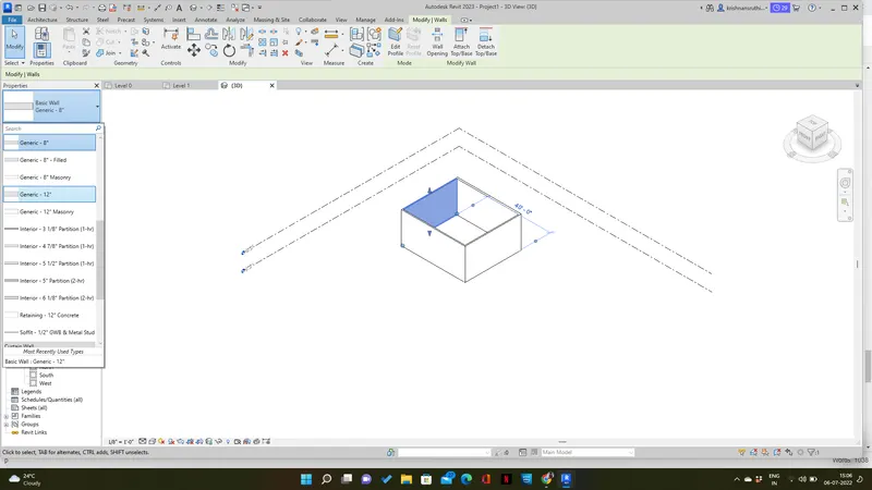
Result: The walls are switched to different types using the property browser
Q6)Aim: To create a 3D view from the view toolbar and save the views with appropriate names.
Introduction: Create a 3D view and save the view to show how the rectangular layout is in 3D in different views.
Procedure:
Step 1: Select the default 3D view from the view toolbar
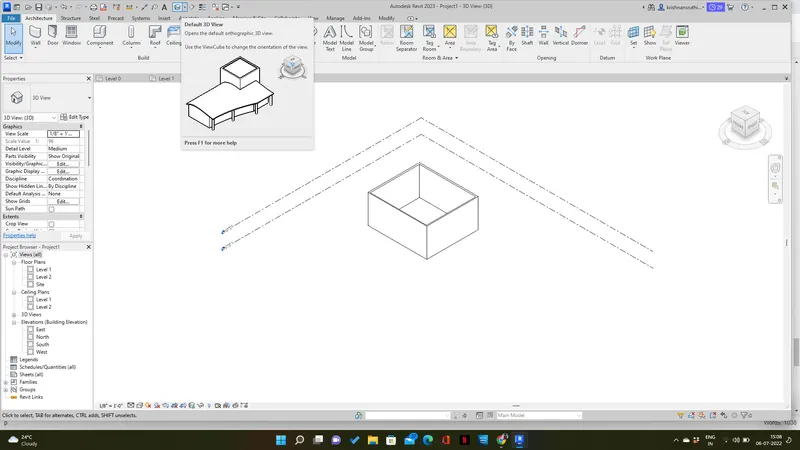
Step 2:Click the view cube and right-click the view want to save
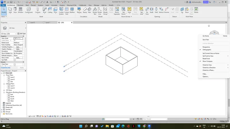
Step3: Select the save view and a new dialog box will appear to save the view with a proper name
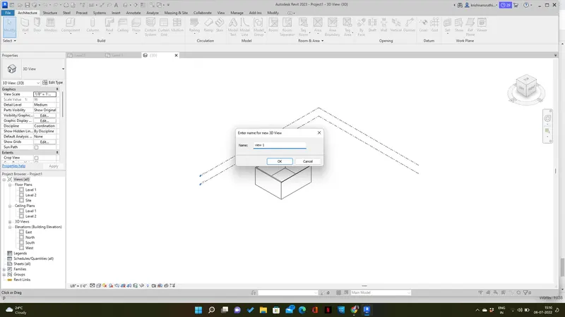
Result: created a 3D view and save the view with the appropriate name.
Q7)Aim: Using view cube orbit or pan through the 3D model
Introduction: There is a steering wheel in the view cube using that we can pan, and orbit the 3d model.
- Using this we can view the different views of the 3D model.
Procedure:
Step 1: Select view from the menu bar
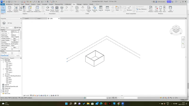
Step 2:Select user interface and select the navigation bar
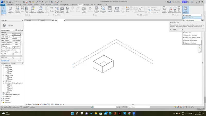
Step3: A steering wheel will appear, using that pan or orbit or zoom the model created
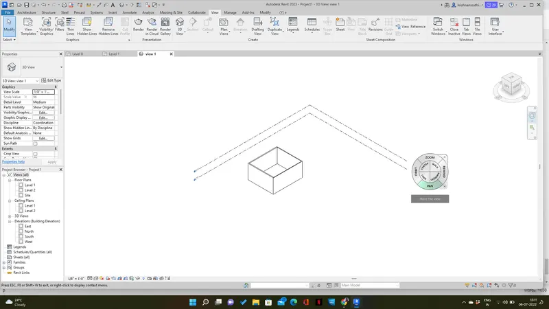
Result: Using steering wheel orbit and pan the 3D model.
Q8)Aim: Switch model to shaded, realistic, etc..using visibility settings
Introduction: Using graphic display settings we can switch the 3D model to wireframe, shaded, realistic, etc.
Procedure:
Step 1: Select visual style from the bottom toolbar
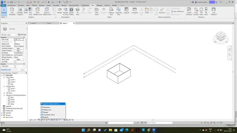
Step 2:Select shaded option
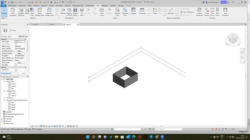
Step 3:Select realistic option
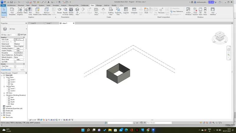
Result: Switch the shaded, realistic styles in the 3D model.
Q9)Aim: To turn the sun path on and off to view shadings in the layout
Introduction: Sunpath shows the direction of the sun according to the building.
- It helps to know the sun's position at any time in our building.
- We can change the settings according to the place where we need to construct the building.
Procedure:
Step 1: Select sun path from the bottom toolbar and click sun path on
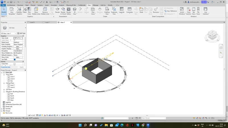
Step 2: Select sun path from the bottom toolbar and click sun path off
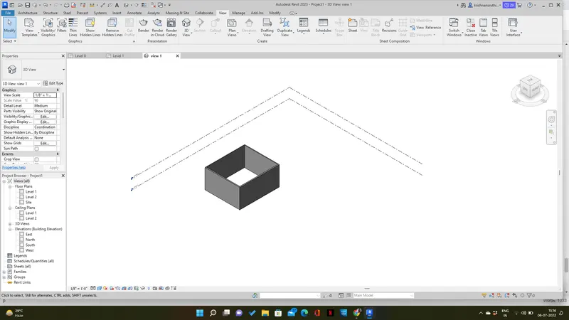
Result: The sun path is turned on and off and shadings are displayed in the layout.
Q10)Aim: To enter project settings, project name, and project issue date using the manage toolbar.
Introduction: By using the manage toolbar we can understand the project information, project name, issue date, etc.
Procedure:
Step 1: In the menu, toolbar select the manage tab
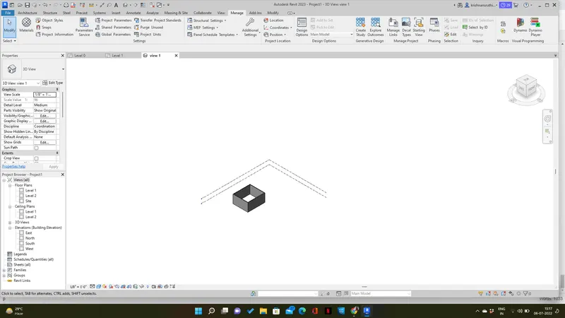
Step 2: Select the project information.
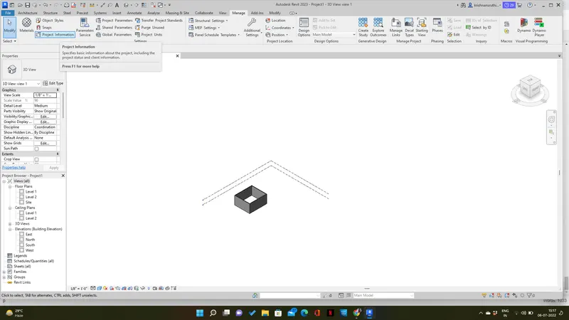
Step 3:new dialog box visible and edit the project settings, name, issue date, etc.. and click ok
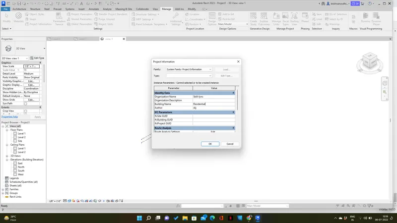
Result: Details of the project entered using the manage toolbar.
Q11) Analyze toolbar in Revit helps us to analyze the structural building. it helps to define load cases, load combinations, and boundary condition settings.
Boundary conditions define point, line, and area boundary conditions in an analytical model. it verifies the boundary condition family types that are loaded or assigned in a structural setting
Load applies point, line, and area loads to a model. Each load geometry is a family containing instance and type parameters, Apply loads by sketching or using host components.
Q12) Link Revit: A Revit project is linked to another current Revit project which is in any discipline such as architecture, structure, MEP, etc.
Link IFC: Link an IFC file to the current project to reference its information for additional design work.
Link CAD: A CAD file linked with the current Revit project.
Link topography: Link existing topography to the current Revit model.
Q13) Collaborate tab in Revit means work sharing.
- It helps us to work together who work in different disciplines such as architecture, structural, and system engineers.
- We can combine the work in the different work contexts in the same project.
- For Example, It is possible for a system engineer can work together with a structural engineer while designing the columns, footings, etc.
- Collaborate tab helps to work together, work sharing, cloud sharing, and central model.
- Working together means we can link the Revit project to another Revit project in a different discipline.
- Work sharing means creating a cental project from an existing model/central model and beginning work in a team.
- it helps the engineers to work efficiently and easily. When we work together if anyone can edit their work it doesn't affect the other person.