Week 9 Challenge
Aim of The Challenge : To Model & Analyse the Bridge Section which is having span of 12.0m length for Wave Load acting on the bridge having Width of Deck Slab 9.0 m, The deck of the slab is supported by 3 I Girders. Each I Girder is 1.7 m height with a top and bottom flange width of 2.5m. The thickness of flange and web is 500 mm The Span of the bridge is 12m having depth of 2m.
Also we have to assume Wave Load Calculation constant r as 5. Assume Cva as 3. The Storm elevation is 8.5m. Take Cr as 0.4.
Introduction : As we Know Staad Pro is Designed and Maintained by Bentley Systems Software Company, Staad Pro is used for Structural Analysis and Design Purposes, As the Given Structure is a Bridge of 12m span, we have to analyse the structure for Wave Loads and briefly describe the analysis results.
Procedure :
Calculations :
Calculation of Wave Loads:
We have to calculate Δzh and Δzv
Δzh = ηmax-Centroid of I girder = 3 -(1.7/2) = 2.15 m
Δzv = ηmax-Elevation of Bottom Deck = 3 -1.7 = 1.3 m
Vertical Load Fv = R x Δzv x Av = 5 x 1.3 x (9 x (1.7/2)) = 50 Kn
Horizontal Load Fh = R x Δzh x Ah = 5 x 2.15 x (2 x 12) = 258 Kn
Max Vertical Load Fvmax = Cva x Fv = 3 x 50 = 150 Kn
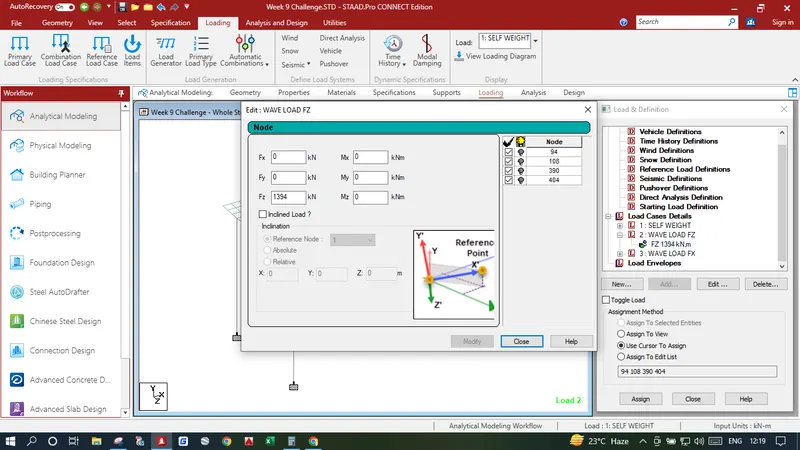
Max Horizontal Load Fhmax = (1+Cr x (N-1)) x Cva x Fh = (1+0.4 x (3-1)) x 3 x 258 = 1394 Kn
Modeling :
- 1. Open Staad Pro and Create a new Project and select Metric in Unit, this will allow us to model the structure in metres as shown in the given diagram and get results in Kn.
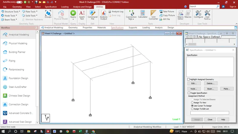
- 2. Input the origin node as 0,0,0 Select the node press CTRL C+ CTRL V input 7 in Y and press ok, create beam between two nodes, again select both the nodes and beam press CTRL C+ CTRL V input 6 in Z and press ok, now select the top left node press CTRL C+ CTRL V input -0.750 in Z and press ok, Similarly select the right top node press CTRL C+ CTRL V input -0.750 in Z and press ok, join all the nodes at top which will create our cross girders now select all the nodes and beams and perform translational repeat number of steps 1 and distance is 12 in X direction, Join top nodes to create a longitudinal girders. After this the model will look like the image below
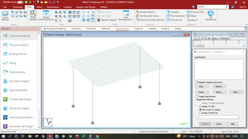
- 3. Create a Deck Slab Select the Origin Node (0,0,0) press CTRL C+ CTRL V input -1.5 in Z press ok again select this node press CTRL C+ CTRL V input 0.5 in X press ok , Select both the nodes press CTRL C+ CTRL V input 0.5 in Z and press ok. Create a Plate Inside these nodes select the plate and perform translational repeat number of steps 23 and distance is 0.5 in X direction, again select all the plates and perform translational repeat number of steps 18 and distance is 0.5 in Z direction which creates our Deck Slab.Which is Shown in the Image Below.
- 4. Now we can have to Provide Supports in Pier Bottom Select all the bottom Nodes Click on Specification in Upper Tab Create a Fixed Support and Assign the Bottom Nodes to Fixed end Support.
Assingning Specifications :
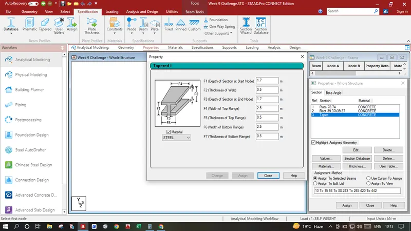
- 1. Click on Specification Tab click on Define click on Rectangle Add a Pier and cross girder size of YD - 1, ZD - 1 m. Click Add, Again Click on Thickness and add a plate of 2 m click ok. Again Click on Define Click on Tappered I Assign the Longitudinal Girders as shown in the image below.
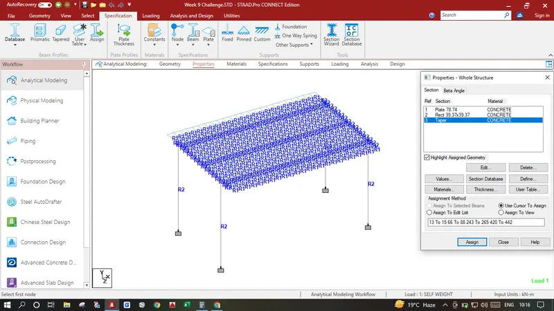
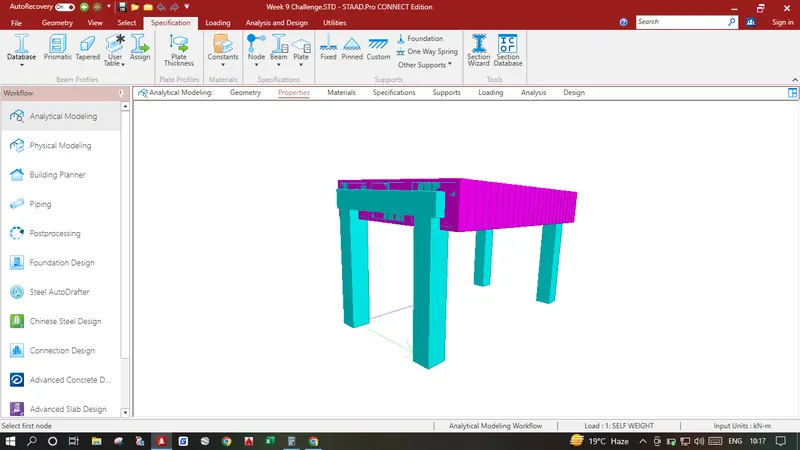
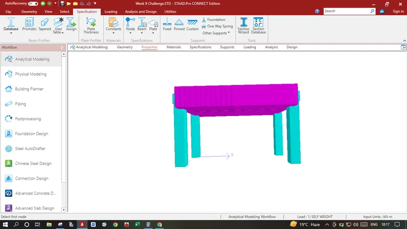
- 2. Select All the Piers and Cross Girders Click on Select click on Parallel under Beams click on parallel to Y and Z which selects both Piers as well as Cross Girders. Assign the Specification having YD - 1, ZD - 1 m Configuration, Similarly Click on Select click on Parallel under Beams click on parallel to X Which selects all the Vertical Girders and Assign the Specification having Tapered I Section Configuration, Also Select all the plates and assign the Specification having plate 2 m Configuration.After assigning all the properties the model should look like the image provided below.
Adding Wave Load:
- 1. Click on Load Cases Details Click add write name Self Weight click add. Again click add and provide sewlfweight in -Y Direction.
- 2. Click on Load Cases Details Click add write name Wave Load FZ click add. Again click add click nodal load and follow the image below.
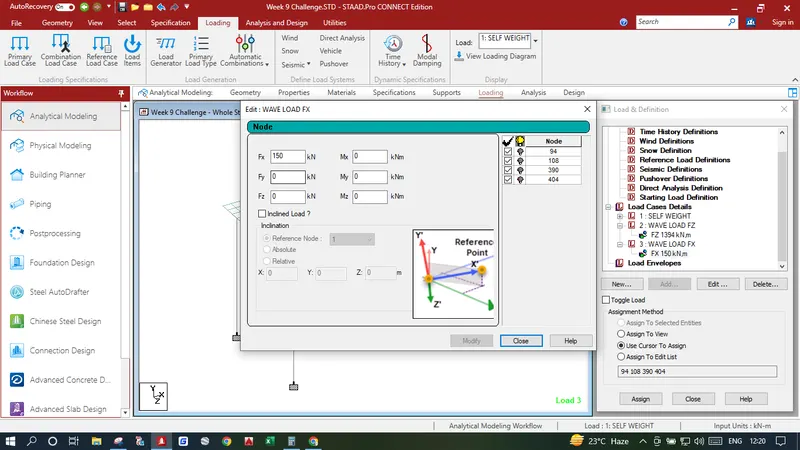
- 3. Click on Load Cases Details Click add write name Wave Load FX click add. Again click add click nodal load and follow the image below.
Analysis & Results :
- 1. Click on analysis and design run analysis, again go to post processing
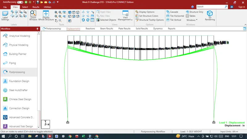
In Results Tab Displacement Pattern show in the image below
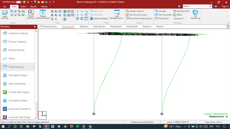
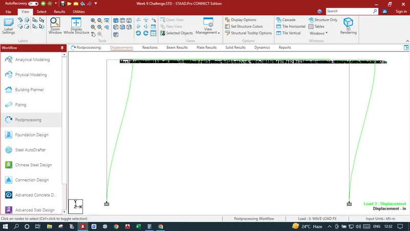
In Results Bending Moments shown in the image below
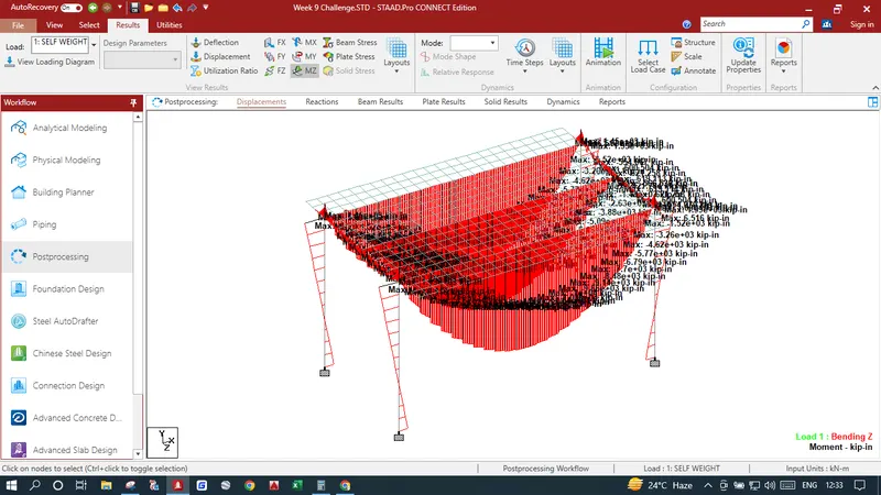
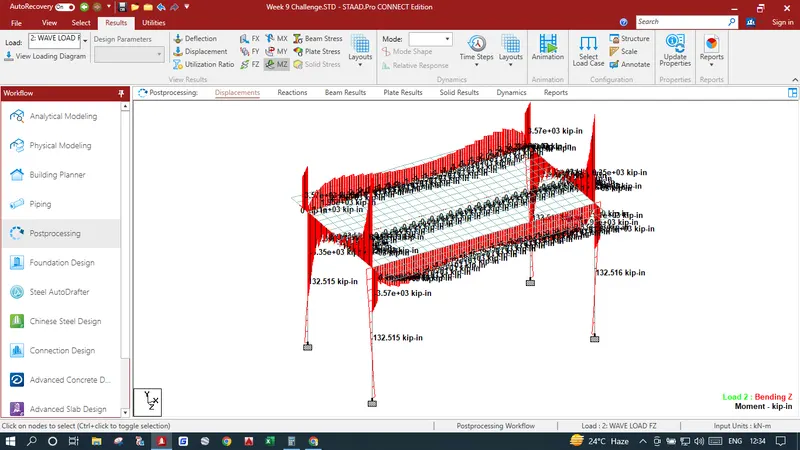
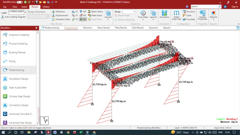
In Results Shear Stresses are shown in the image below
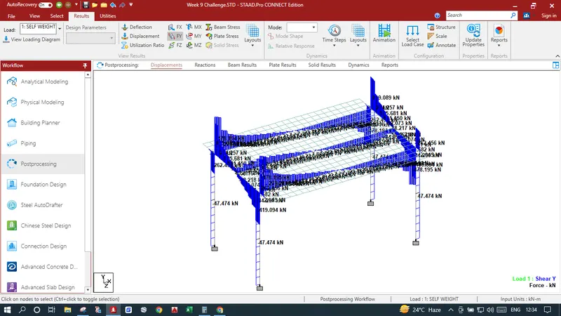
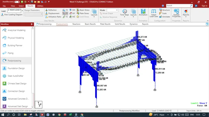
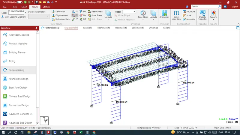
In Results Plate Stresses in MY Local are shown in the image below
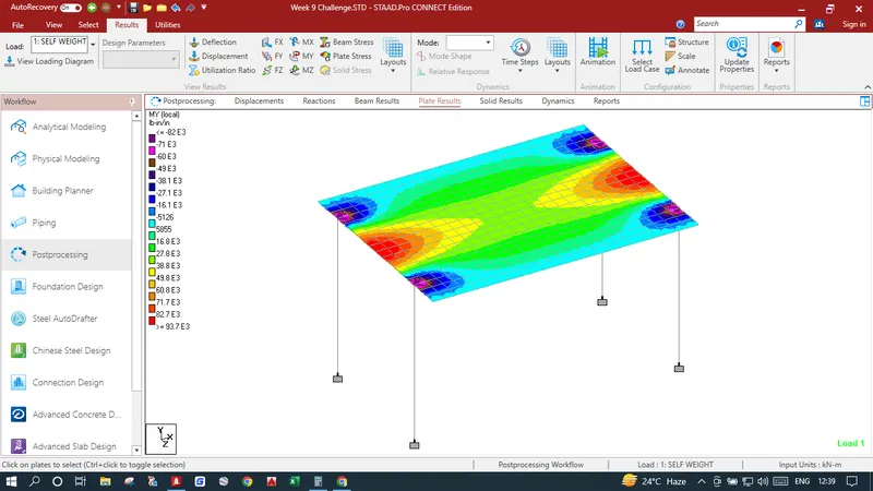
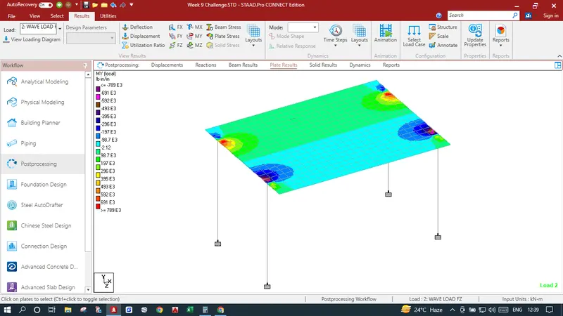
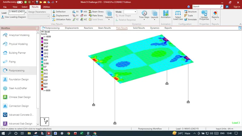
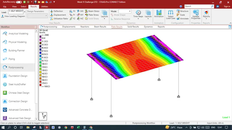
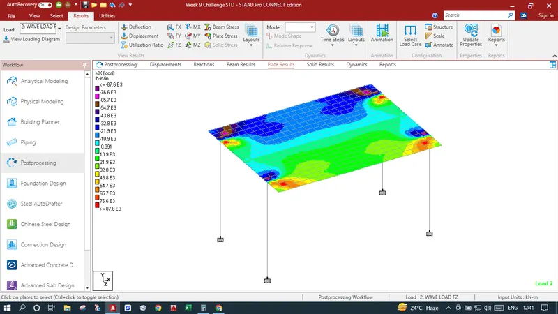
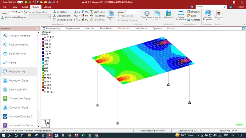
In Results Plate Stresses in MX Local are shown in the image below