Week 4 Challenge
Aim of The Challenge : To Model & Analyse the Given Abutment wall section in the Staad Pro and Brielfy Identify The Plate Stresses Developed on the wall while subjecting to Earth Pressure loads also identify the displacement direction of the wall.
Introduction : As we Know Staad Pro is Desinged and Maintained by Bentley Systems Software Company, Staad Pro is used for Structural Analysis and Design Purposes, As the Given Structure is a Abutment wall we have to analyse the structure for Earth Pessure Loading and briefly describe the analysis results.
Procedure :
Modeling :
- 1. Open Staad Pro and Create a new Project and select Metric in Unit, this will allow us to model the structure in metres as shown in the given diagram and get results in Kn.
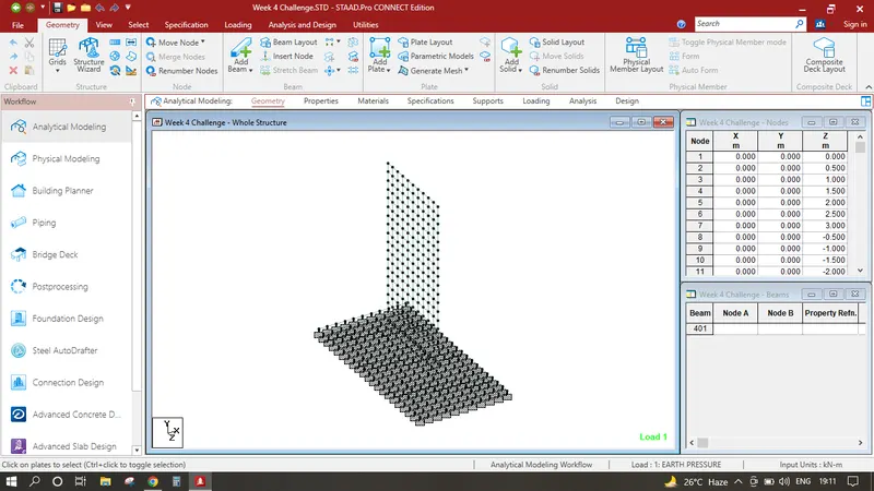
- 2. Input the origin node as 0,0,0 for and select the node press CTRL C+ CTRL V input 0.5 in Z and press ok, select both the nodes press CTRL C+ CTRL V input 0.5 in Y and press ok, this will create the square shape add plate inside select this plate and perform the translational repeat number of steps 5 and distance is 0.5 in Z direction similarly perform in opposite direction number of steps is 4 and distance is -0.5, by performing this procedure this will create the abutment wall bottom section but as we can see the the earthpressure loads are subjected to 7m in height therefore select all the bottom plates and again repeat the translational repeat command as height of the wall is not gven we are assuming it as a 10m input number of steps 19 and distance is 0.5 in Y direction this creates the full abutment wall of 10m height.
- 3. Now we can see the wall is supported by bottom foundation of depth 1m we have to create the bottom plate mesh select the origin node (0,0,0) and press CTRL C+ CTRL V input 0.5 in X and press ok now select the node which is in X direction and origin node as well press CTRL C+ CTRL V input 0.5 in Z and press ok create a plate inside the square now select this plate and perform translational repeat no. of steps 4 distance 0.5 in X direction select the newly created bottom plates and perform similarly in in Z direction and -Z direction this creates all the foundation plates in +x direction similarly repeat plates in -X direction which creates all the plates at the bottom.
Assingning Specifications :
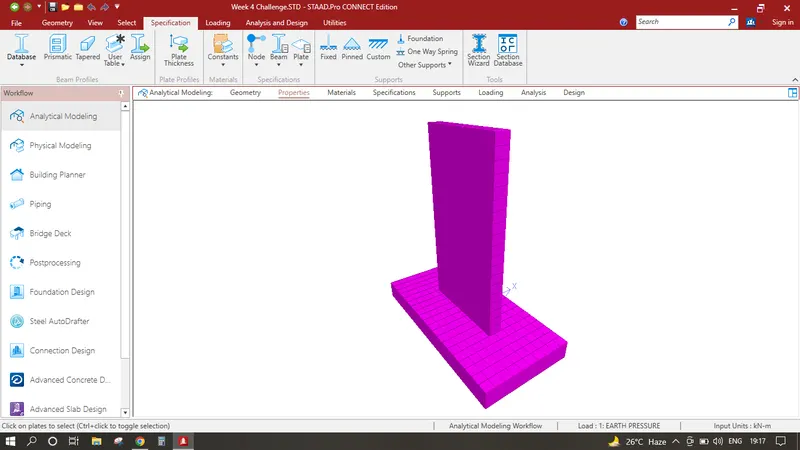
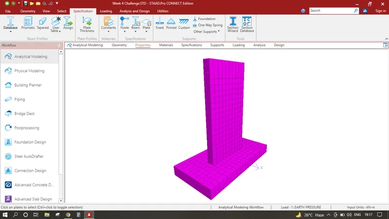
- 1. Click on Specification Tab click on Plate Thickness add 0.7 click ok, similarly click plate thickness again add 1.0 click ok, this creates 2 plates of two thickness.
- 2. Select all the vertical plates which is abutment wall and assign the plate category having thickness 0.7m , similarly select the all the foundation plates and assign it to the plate category having thickness 1.0m. Finally Profide the Support Select all the Bottom plates and assign it to fixed end supports after assigning all the properties the model should look like the image provided below.
Adding Earthpressure Loadings:
- 1. Click on Loadings click on Load cases details Click add Under Primary Loads Write Earth Pressure click add
- 2. Click on Earth Pressure click add click on plate loads then hydrostatic loads click on select plates, select the abutment wall plates to the very left corner upto the height of 3m which is 6 plates towards Y direction, In W1 which is maximum load should be provided 54 Kn/m2 (Unit Weight of Soil 18 Kn/m2 and upto the height of 3m = 18 x 3 - 54), In W2 write 0, Interpolating along Y and Direction of Pressure is GX click add this creates different earth pressures of 54Kn/m2 to 0 interpolated along height of 3m.
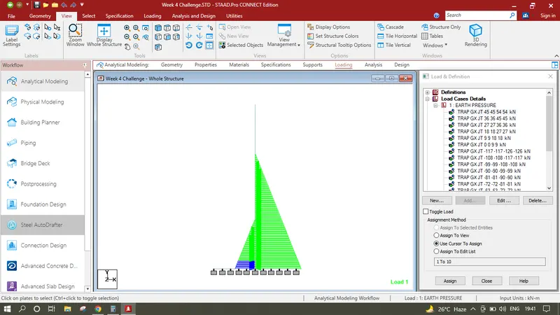
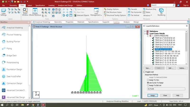
- 3. As the loading applied in only one row of plates but we have to apply these loading into all the plates in abutment wall, first click on View in uppertab and click onto side view now click on first generated load and the by clicking it turns that plate into blue colour now select the plate in which shows the blue colour as you are in side view all the plates along that row is selected click on assign it to selected plates this will allow the model to apply the first load into all the plates in abutment wall of that row similarly select the second load and repeat the process repeat this process untill you reach the height of 3m By doing this it will allow the model to be subjected to earth Pressure in one side
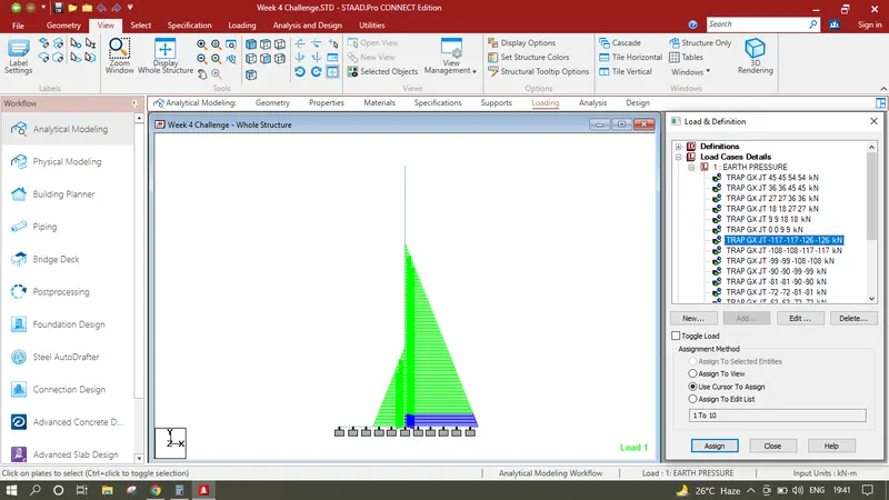
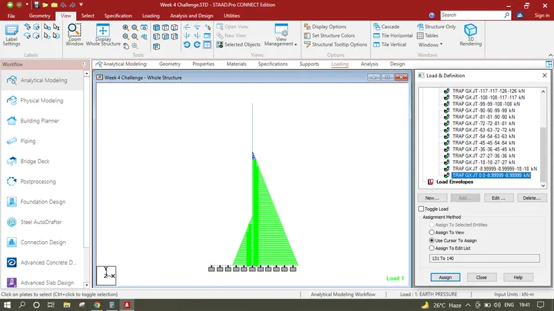
- 4. Now we have to apply Backfill of height upto 7m loading but in reverse direction so that the loads created in point 3 will counteract, again click on Earth Pressure click add select the plate loads and select the Hydrostatic Loads click on select plates,select the plates in extreme left upto the height of 7m i.e. select 14 plates along Y Direction, In W1 which is maximum load should be provided - 126 Kn/m2 (Unit Weight of Soil 18 Kn/m2 and upto the height of 7m = 18 x 7 - 126), In W2 write 0, Interpolating along Y and Direction of Pressure is GX click add this creates different earth pressures of 126Kn/m2 to 0 interpolated along height of 7m.
- 5. As the loading applied in only one row of plates but we have to apply these loading into all the plates in abutment wall, first click on View in uppertab and click onto side view now click on first generated load and the by clicking it turns that plate into blue colour now select the plate in which shows the blue colour as you are in side view all the plates along that row is selected click on assign it to selected plates this will allow the model to apply the first load into all the plates in abutment wall of that row similarly select the second load and repeat the process repeat this process untill you reach the height of 7m By doing this it will allow the model to be subjected to earth Pressure in other side.
Analysis & Results :
- 1. Click on analysis and design run analysis, again go to post processing
In Results Tab Displacement Pattern show in the image below

In Results Plate Stresses along MX Local shown in the image below
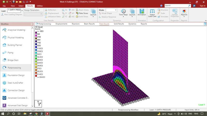
In Results Plate Stresses along MY Local shown in the image below
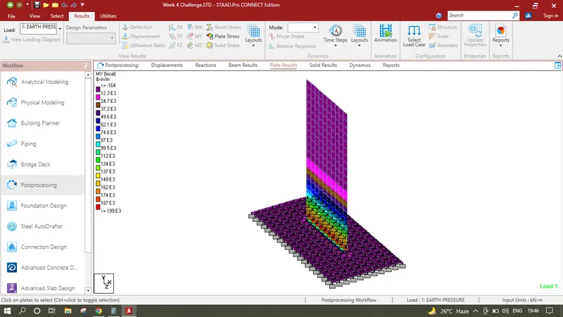
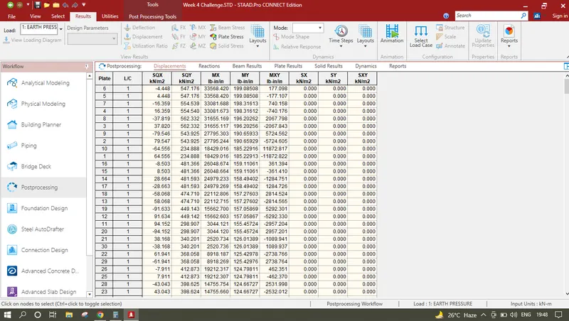
Select all the Plates click on Reports click on plate stresses Click on Bending MX and set sorting order High to Low.
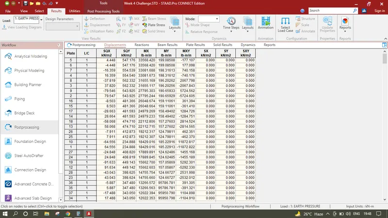
Select all the Plates click on Reports click on plate stresses Click on Bending MY and set sorting order High to Low.