Week 5 Challenge
Aim of The Challenge : To Model & Analyse the Bridge Section which is having the height of 9m and Pier size of 1.5 x 1.5, for Wind Load Condition and Location of the Bridge is Stated above, in Staad Pro and Brielfy Identify The Displacement, Bending Moments & Shear Forces Developed on the Structure while subjecting to Wind Load Condition.
Introduction : As we Know Staad Pro is Desinged and Maintained by Bentley Systems Software Company, Staad Pro is used for Structural Analysis and Design Purposes, As the Given Structure is a Bridge of 9m Pier Height we have to analyse the structure for Wind Loading and briefly describe the analysis results.
Procedure :
Calculations :
Design Wind Speed Vz = Vb x k1 x k2 x k3 x k4
K1 = Probabilty Factor
K2 = Height Factor
K3 = Topography Factor
K4 = Importance Factor
For Vb Refer IS 875 (Part 3) 2015 Annexure A Clause 6.2, As We Can see Mumbai has Vb value of 44
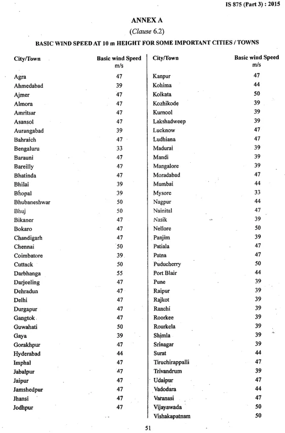
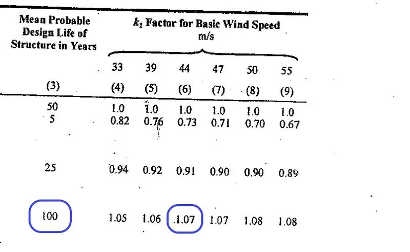
K1 - Probablity Factor Refer IS 875 (Part 3) 2015 Clause 6.3.1, we have to select 100 Years Design Life and For 44 m/s in Mumbai we have to select 1.07 for K1
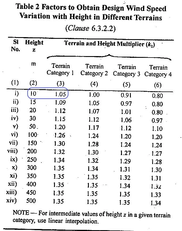
K2 - Height Factor Refer IS 875 (Part 3) 2015 Clause 6.3.2.2 Table 2, As We can see The Structure have a Obstruction Height of 10m and it Belongs to Category 1 we have to select 1.05 for K2
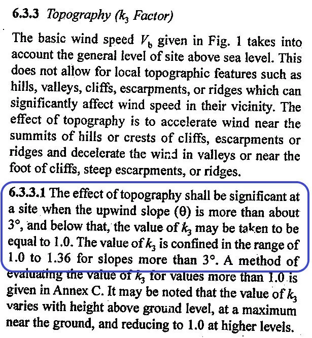
K3 - Topography Factor Refer IS 875 (Part 3) 2015 Clause 6.3.3.1 Paragraph, Select 1.0 for K3.
K4 - Importance Factor Refer IS 875 (Part 3) 2015 Clause 6.3.4 , As Our Structure is a Bridge Structure It Comes under category of Important Structure Therefore, we have to select 1.30 for K4
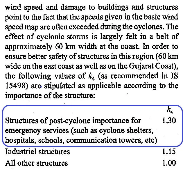
Design Wind Speed Vz = Vb x k1 x k2 x k3 x k4
Vz = 44 x 1.07 x 1.05 x 1.00 x 1.300
Vz = 64.2642 m/s
Wind Pressure Pz = 0.6 x Vz^2
Pz = 0.6 x 64.2642 x 64.2642
Pz = 2565 N/sqm
Pz = 2.477 kN/sqm
Modeling :
- 1. Open Staad Pro and Create a new Project and select Metric in Unit, this will allow us to model the structure in metres as shown in the given diagram and get results in Kn.
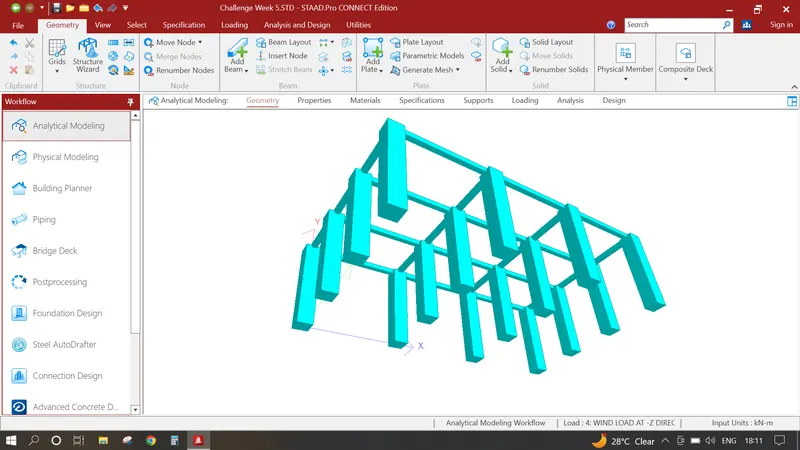
- 2. Input the origin node as 0,0,0 for and select the node press CTRL C+ CTRL V input 9.0 in Y and press ok, Create a Beam select both the nodes and Beam and perform the translational repeat number of steps 3 and distance is 6 in Z direction Similarly Select All the Beams and perform the translational repeat number of steps 3 and distance is 10 in X direction, Connect all the Longitudinal As well as Vertical Beams, By Performing above Steps we have created a Model of 3 Span of 10m having Pier Support at every 6m Which is Shown in the Image Below.
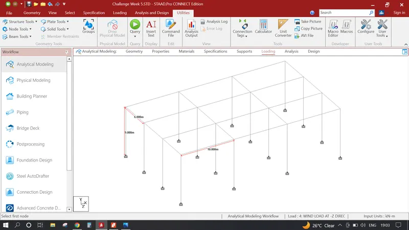
- 3. Now we can have to Provide Supports in Pier Bottom Select all the bottom Nodes Click on Specification in Upper Tab Create a Fixed Support and Assign the Bottom Nodes to Fixed end Support.
Assingning Specifications :
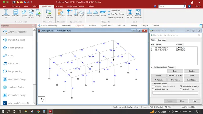
- 1. Click on Specification Tab click on Define click on Rectange Add a Pier Size of 1.5 x 1.5 m Click Add, Again Click on Define Click on Rectange Assign the top Long, Vertical Girders as 0.5 x 0.5 m.
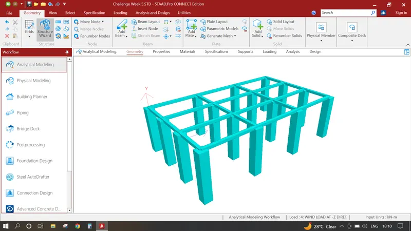
- 2. Select all the Piers and Assign the Specification having 1.5 x 1.5 m Configuration, Similarly Select all the Top Beams and Assign the Specification having 0.5 x 0.5 m Configuration. After assigning all the properties the model should look like the image provided below.
Adding Wind Pressure Loadings:
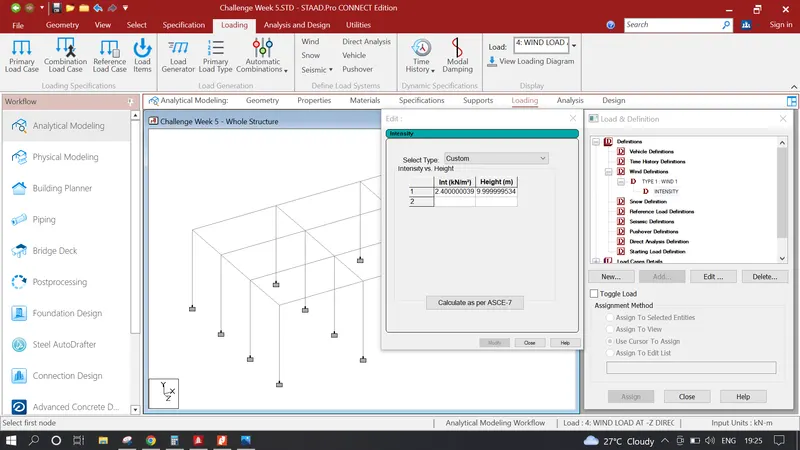
- 1. Click on Loadings click on Definitions Click on Wind Definitions click add Wind 1 Click on Wind 1 Click add Input Value Given in Image
- 2. Click on Load Cases Details Click add Write Name WIND LOAD AT -X DIRECTION TO +X DIRECTION again Click on WIND LOAD AT -X DIRECTION TO +X DIRECTION click add and click on Wind Load and input values as provided
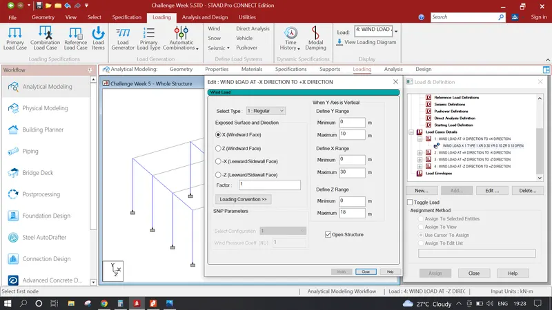
- Click on Load Cases Details Click add Write Name WIND LOAD AT +X DIRECTION TO -X DIRECTION again Click on WIND LOAD AT +X DIRECTION TO -X DIRECTION click add and click on Wind Load and input values as provided
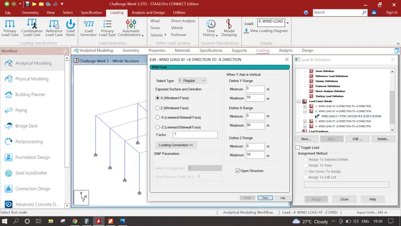
- Click on Load Cases Details Click add Write Name WIND LOAD AT +Z DIRECTION TO -Z DIRECTION again Click on WIND LOAD AT +Z DIRECTION TO -Z DIRECTION click add and click on Wind Load and input values as provided
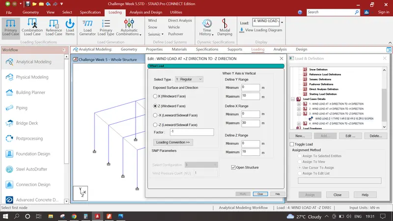
- Click on Load Cases Details Click add Write Name WIND LOAD AT -Z DIRECTION TO +Z DIRECTION again Click on WIND LOAD AT -Z DIRECTION TO +Z DIRECTION click add and click on Wind Load and input values as provided
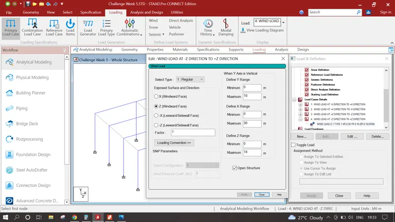
Analysis & Results :
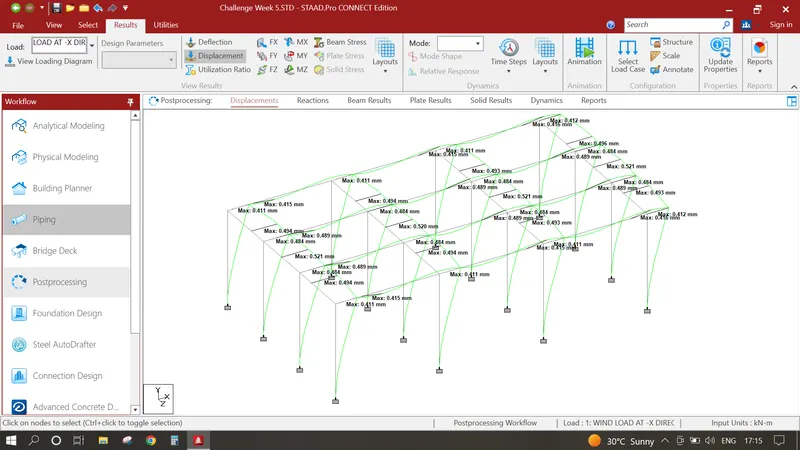
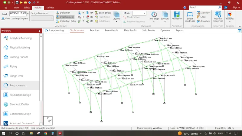
- 1. Click on analysis and design run analysis, again go to post processing
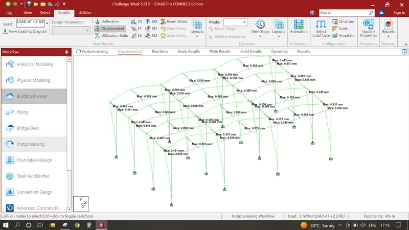
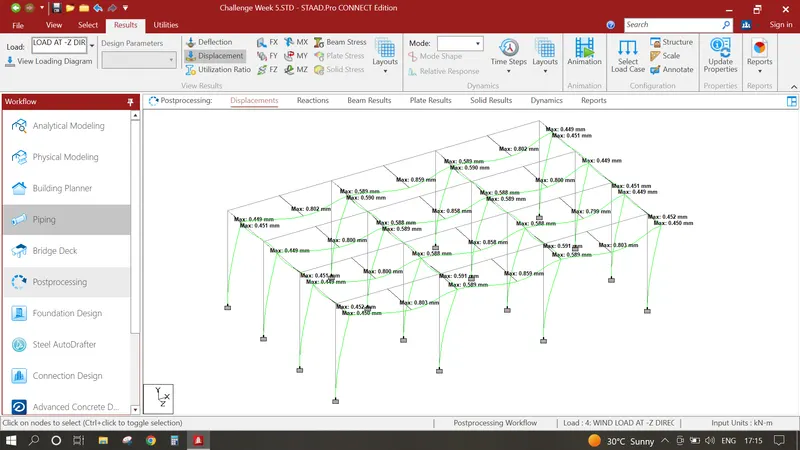
In Results Tab Displacement Pattern show in the image below
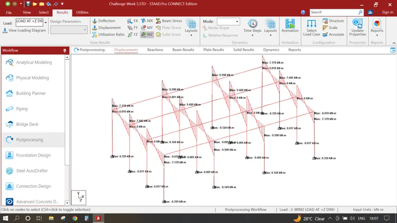
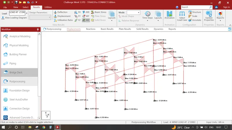
In Results Bending Moments shown in the image below
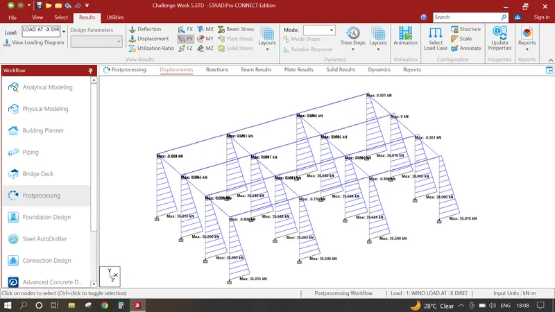
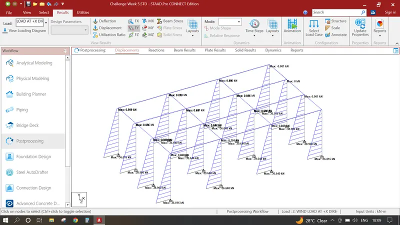
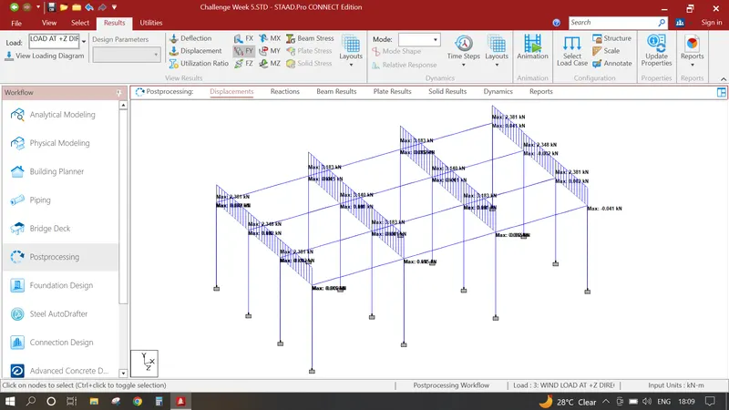
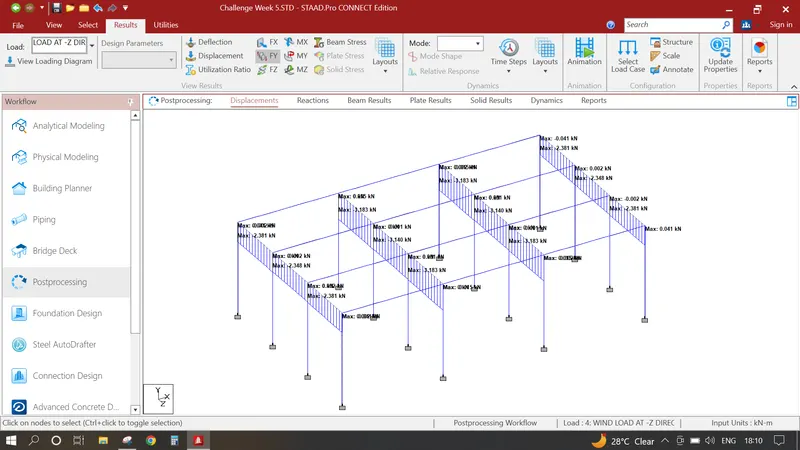
In Results Shear Stresses are shown in the image below