Week 1 Challenge
Aim of The Challenge : To Model & Analyse the Given Box Girder Section in the Staad Pro and Brielfy Identify The Bending Moments, Shear Forces and Displacement Directions of the Members.
Introduction : As we Know Staad Pro is Desinged and Maintained by Bentley Systems Software Company, Staad Pro is used for Structural Analysis and Design Purposes, As the Given Structure is a Box Girder Bridge Slab we have to analyse the structure for its dead loads conditions occuring from the given superstructure.
Procedure :
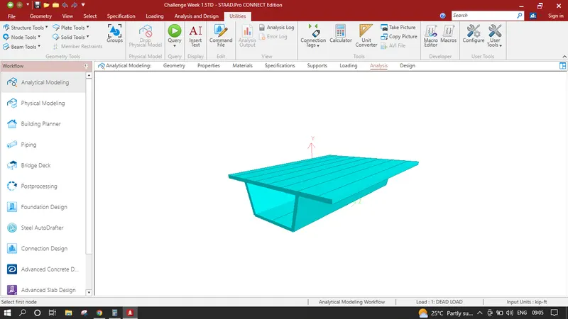
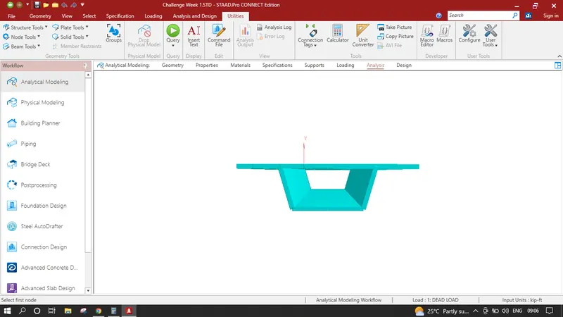
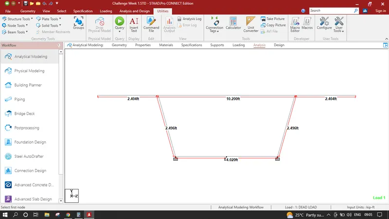
- Modeling1. Open Staad Pro and Create a new Project and select English in Units.2. Input the origin node as 0,0,0 for Lower deck slab which is of 4.020 in measurement add node as 2.010 & -2.010 in Z direction.3. Now from the origin point (0,0,0) add node 2.400 in Y direction which acts as a center point of the main deck slab.4. Add Node in Z direction at a distance of (1.361+1.200+(0.269/2)) 2.6955 and -2.6955 these two nodes act as a joining point of lower deck slab.5. Join the nodes created in point number 3 to the newly created nodes in point number 4 which creates a box type of model.6. As the Width of deck slab provided is 10.200 create a node from the center point of the main deck slab in Z direction 5.100 and -5.100 which completes our geometrical model as shown in the image below.
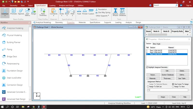
- Specifications1. As the Length of the Superstructure given is 12000 we have to create 3 different definitions.2. Click on Specification Tab on top and in small window click define, select Rectangle and create a Section definition R1 as (YD- 0.25, ZD- 12), Similarly R2 as (YD- 0.25, ZD- 12) Also R3 as (YD- 0.2, ZD- 12).3. Select the Top Deck Slab and assign it to R1 by click in to Assign to selected beams, Now select the sloped beams and assign it to R2, Finally select the bottom Slab and assign it to R3. Refer the Image Given Below.4. Add Support Click on Fixed Support and add, click on the click cursor to assign option and assign the supports in lower deck slab's Mid and both ends as shown in the image below.
- Loadings1. Click on Loadings in Upper Tab and in the right side click on load cases details and click on add, write the title name as Dead Load and select the loading type as Dead Load.2. A new Load Case has been created click on dead load and click add, select the self weight and direction would be Y and factor would be -1.3. Click on Self weight and assign the loading by clicking in to Assign to view.
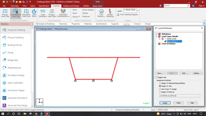
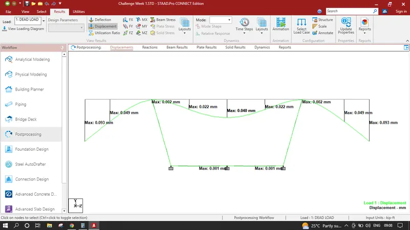
- Analysis & Results1. Click on Analysis and Design in Tab on Top click on define commands on right, click on perform analysis tab and click add. Click on Run Analysis Button, again click in postprocessing to get the results.In Results Tab Displacement Pattern show in the image below
- 2. For Annotations Marking Click on Annotate, click on beam results and annotate as per your diagram i.e. if you are willing to annotate the displacements click on Max Resultants under displacement and click annotate similarly for bending moments and shear forces.
In Results Tab Displacement Pattern show in the image below
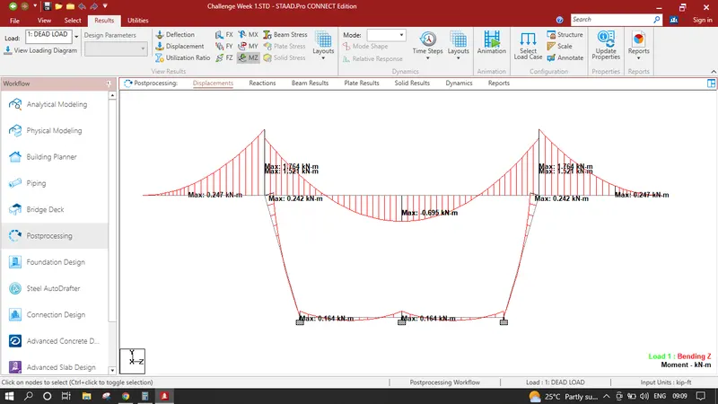
In Results Bending Moments shown in the image below
In Results Shear Forces shown in the image below
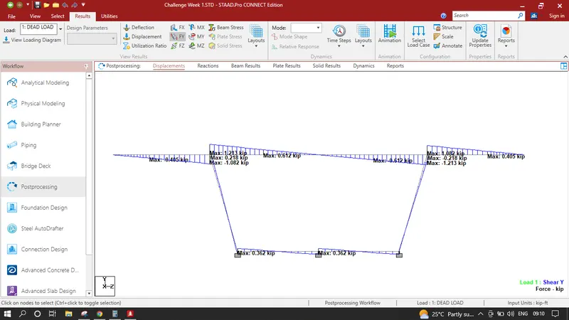
As we can see there is very less displacement as well as bending moments and shear forces that is due to fact that we only applied Dead Loads which is the self weight of the structure as we apply more loadings such as - Live loads, Wind Loads Water Current Loads, Seismic Loads etc. the value of Displacement, Bending Moments and Shear Forces Vary in large numbers. We use these Annotated Maximum Values for the Detailed Design of the Structure.
Below is the Staad Input as well as i am attaching the staad file
STAAD SPACE
START JOB INFORMATION
ENGINEER DATE 08-Oct-22
END JOB INFORMATION
INPUT WIDTH 79
UNIT FEET KIP
JOINT COORDINATES
1 0 0 0; 2 0 0 4.02; 3 0 0 2.01; 4 0 2.4 2.01; 7 0 2.4 4.7055; 8 0 2.4 -0.6855;
9 0 2.4 3.371; 10 0 2.4 0.649; 11 0 2.4 6.21; 12 0 2.4 -2.19; 13 0 2.4 -3.09;
14 0 2.4 7.11;
MEMBER INCIDENCES
1 1 3; 2 3 2; 4 4 9; 6 8 10; 7 8 1; 8 2 7; 9 9 7; 10 10 4; 11 12 8; 13 7 11;
14 13 12; 15 11 14;
DEFINE MATERIAL START
ISOTROPIC CONCRETE
E 453600
POISSON 0.17
DENSITY 0.14999
ALPHA 5.5e-06
DAMP 0.05
TYPE CONCRETE
STRENGTH FCU 576
END DEFINE MATERIAL
MEMBER PROPERTY AMERICAN
4 6 9 TO 11 13 TO 15 PRIS YD 0.25 ZD 12
7 8 PRIS YD 0.25 ZD 12
1 2 PRIS YD 0.2 ZD 12
CONSTANTS
MATERIAL CONCRETE ALL
SUPPORTS
1 TO 3 FIXED
LOAD 1 LOADTYPE None TITLE DEAD LOAD
SELFWEIGHT Y -1
PERFORM ANALYSIS
FINISH