Week 9 Challenge
1.Introduction:-
Wave load are load induced by sea wave on bridge . Wave load are two type loading one is horizontal load trust on pier and horizontal part of pier. Vertical Load are from bottom to slab of bridge.We calculate the load by imperical formula as given in IS code.
2.Aim:-
Here we given the bridge near the sea ,so we need the calculate the wave load effect on bridge. Here some values need before calculate load due to wave load on bridge.
As max crest elevation , Cr for horizontal and vertical .
3.Procedure :-
For wave load calculate we need some data before calculate load on bridge
According to IS 4651
Max of vertical wave load
(Fv)max =Cva-v(Fv)*
Here `Fv*=gamma(DeltaZv)Av`
where ,
Av=area of bridge contributing to vertical uplift
Zv= Difference between elevation of crest of max wave and elevation of underside of bridge deck
r=Unit weight of water
Max of horizontal wave load ,
(Fh)max=[1+Cr(N-1)]Cva-hFh*
Here
Fh*=Horizontal wave load
=r(Delta Zh)Ah
These are quation which use for calculate wave load on bridge .
Here given Data are such as
1.max crest elevation for the wave =3m
2.No of girde =3
3. Height of girder =1.7 m
4.Span of Bridge =12m
5.Width of bridge =9m
6.Slab thickness =2m
7.Reduction coefficent =0.4
8.Width of top and bottom flange =2.5m
9.Thickness of Flange and web =0.5m
10.Density of water as given =5 Kn/m
`DeltaZv`=n-Elevation of bottom deck
=3-2
=1
Av= Area of bridge contributing to vertical uplift
=7*1
=7 (for unit length )
r= Density of water
=5kn/m3 (Given )
so,
max vertical load
`nbsp; =10*1*(9*(1.7+2)/2)`
= 83.25 kn
For Max of vertical wave induced load
=Crv*Fv*
= 3*83.25
~249.75
=250 kn
horizontal load
`nbsp; =5(3-0.850)*(12*1.85)`
`nbsp; =238.65 kn`
So ,
Max horizontal wave induced load
=[1+0.4(3-1)]*3*238.65
=1288.71
=1290 kn
So these (Colour Data) values need to apply the model as per given data .
Now as per given data we create the model for load results calculation
Open the Staad pro and create the model step by step
1.Select the locaion of file and create the file name
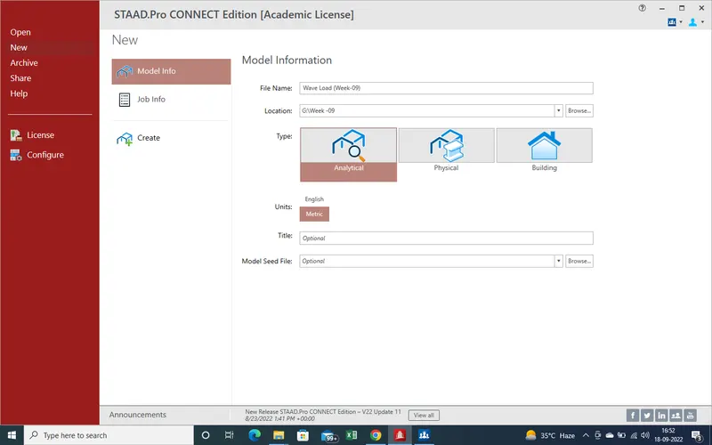
2.As select the Create main window has been opened
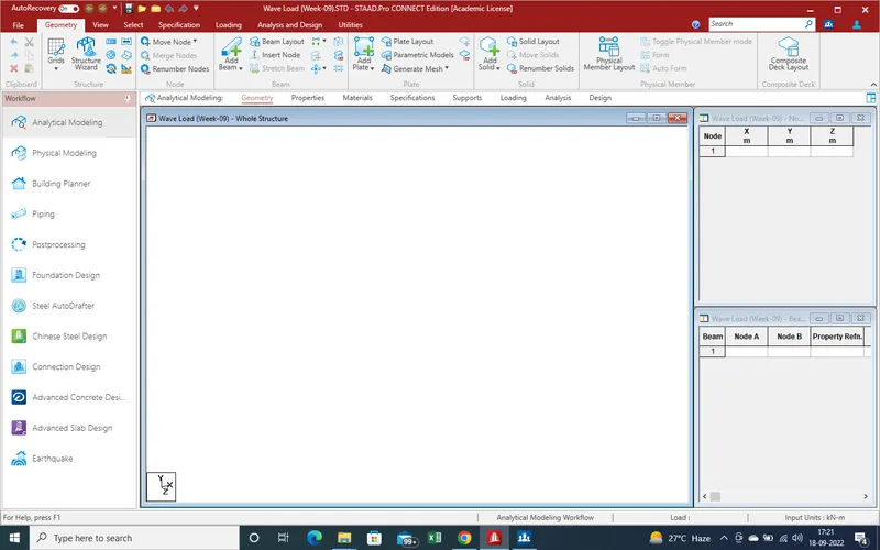
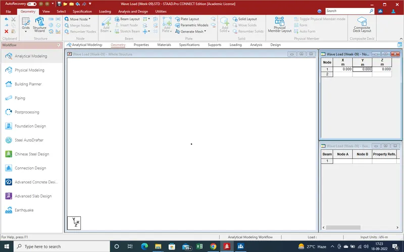
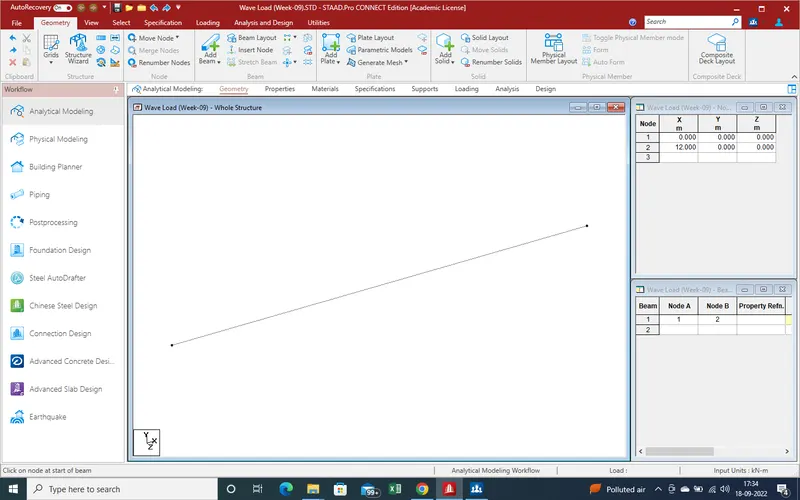
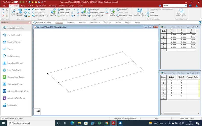
3.Start modeling from 0,0,0 node
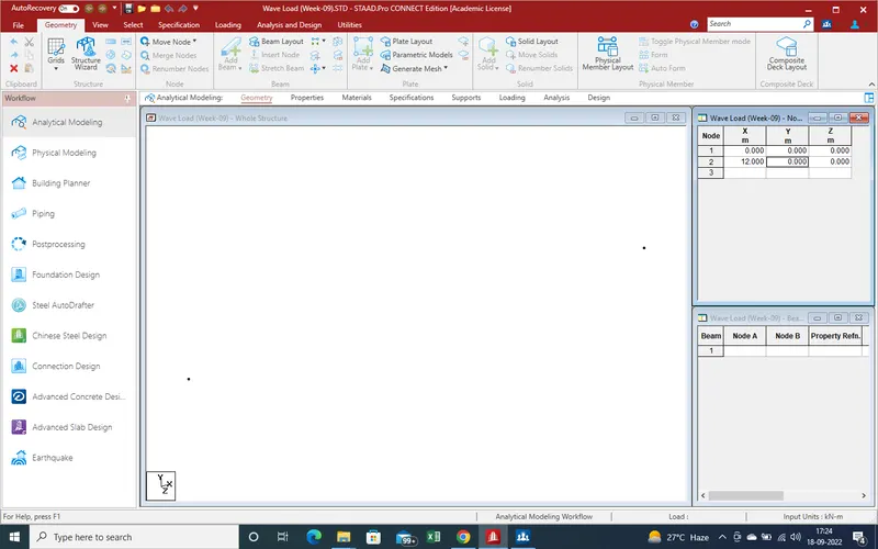
4.As Span is 12 mtr so create second node at 12mtr distance
5.Now with the help of "Add Beam " create the beam between given two nodes for main girder
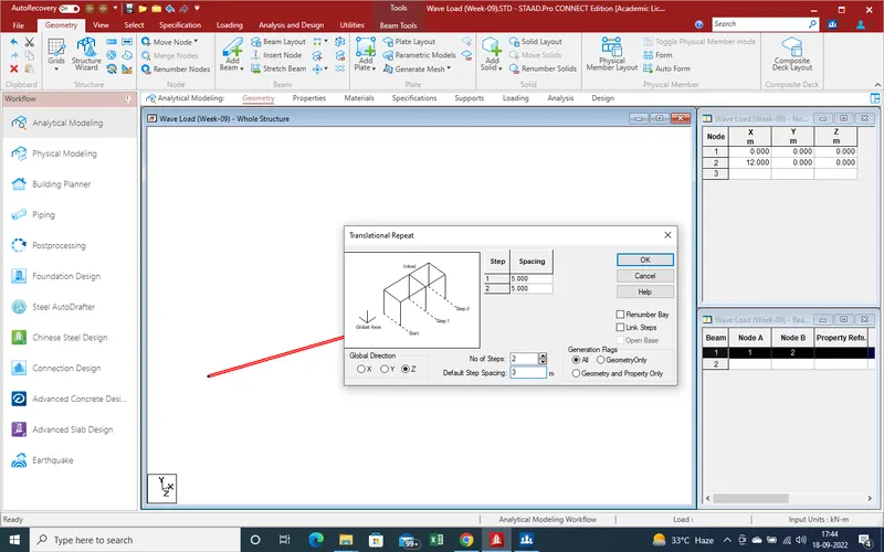
6.As given data ,there are 3 nos girders with same spacing and same length ,so we can use the translation repeat command .
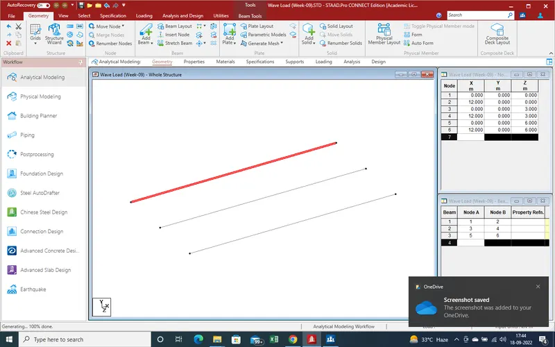
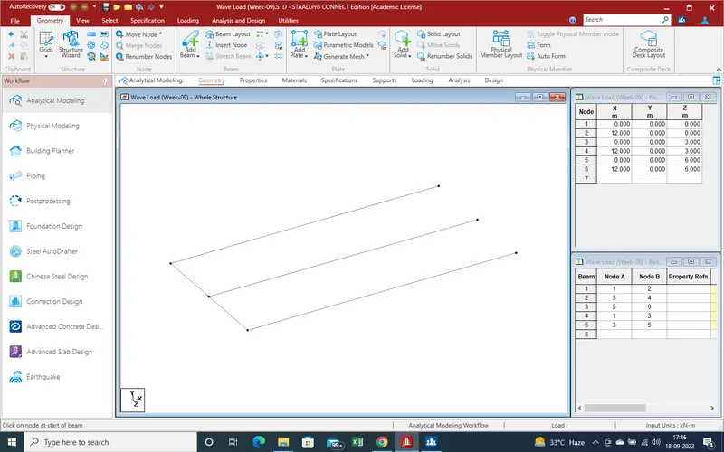
7. Joint the main girder with help of cross girder by add beam command
8. Now define the properties for main girder and cross girder with help of properties
section as properties for main girder are such as top and bottom flange are 2.5m and thicness for 0.5m for web and flange
but there is no data for cross girder so we assume that thickness 0.3m and depth 1m .
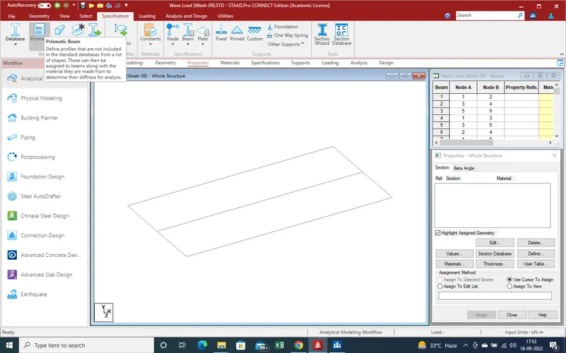
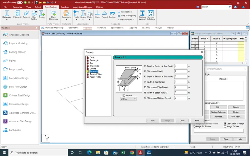
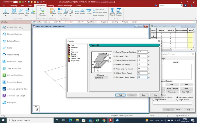
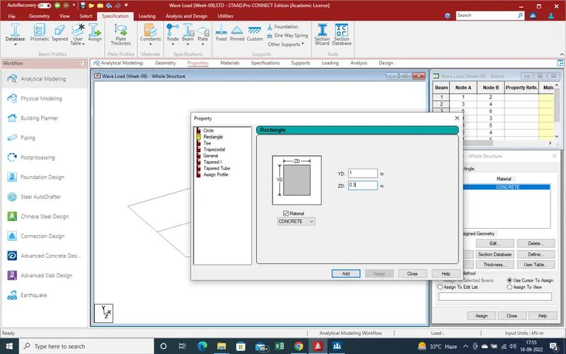
9.Now properties has been created so, now assign the properties for main girder and cross girder
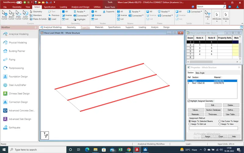
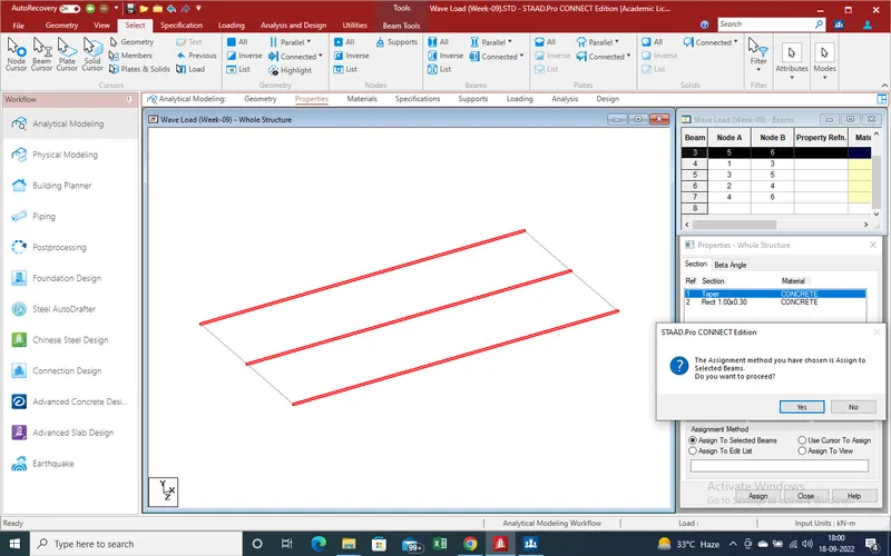
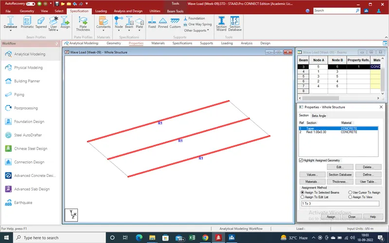
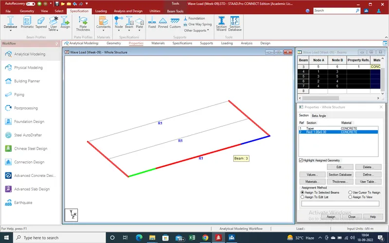
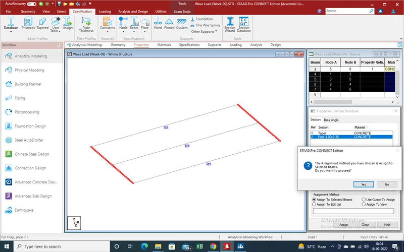

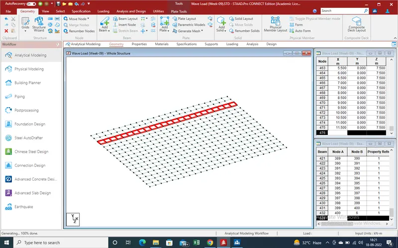
10. Main girder and cross girder has been created ,now create the slab with help of plate nodes . we create the plates section of 0.500m *0.500m size so we can get the plates results we more accuracy
for create the plate section need 4 nodes so with help of translation repeat command for node create after 1 plate section same process repeat for plates section
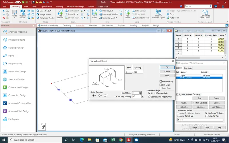
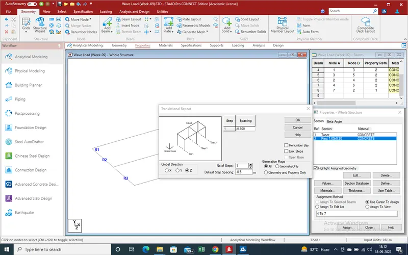
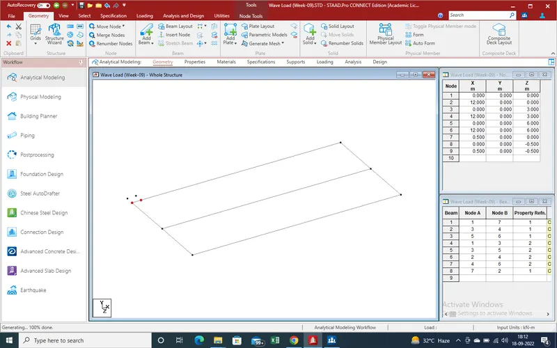
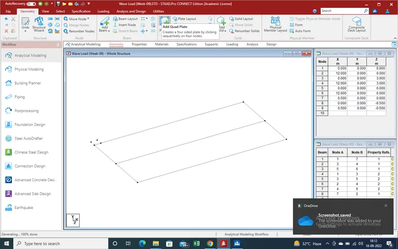
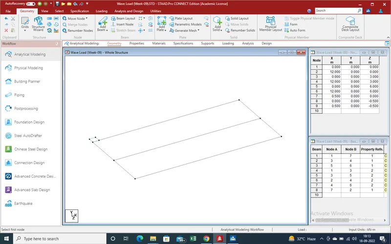
11.As one plate has been created with the help of translation repeat command create slab over girder
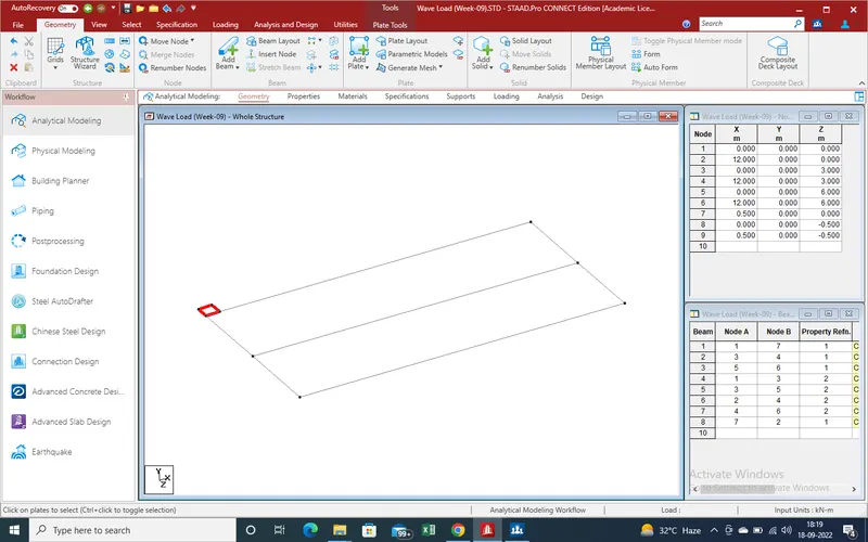
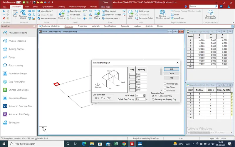
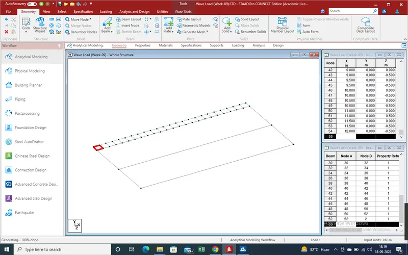
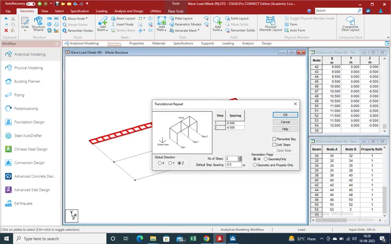
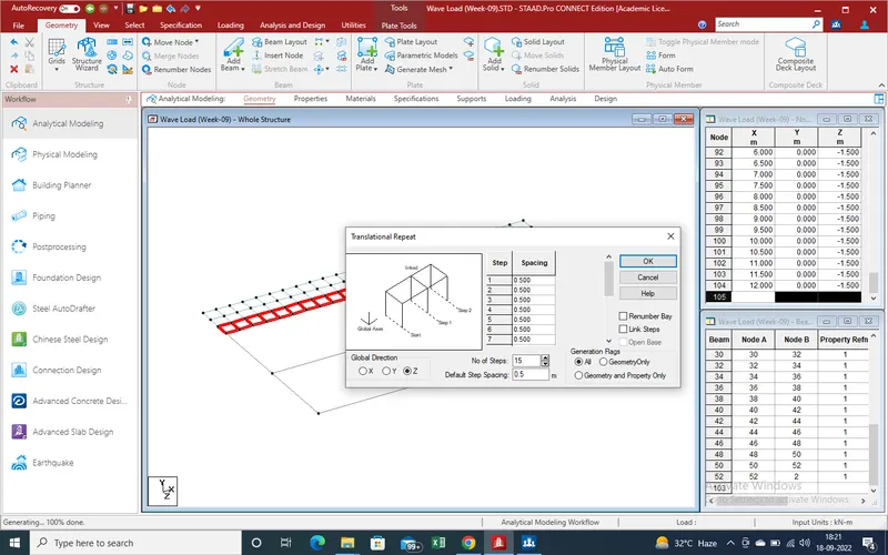
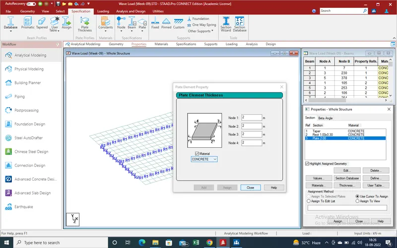
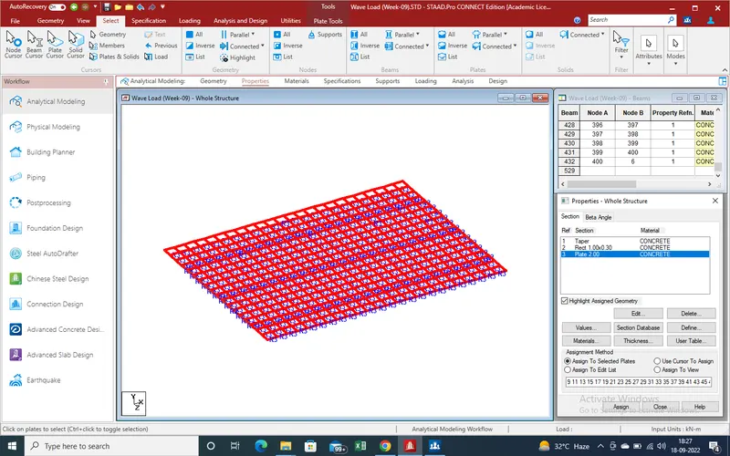
12. Now define the properties for plate and assign
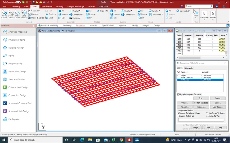
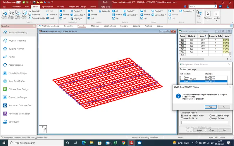
13.Now Apply the Support Rection as slab on pier are as pinned support so define support and apply
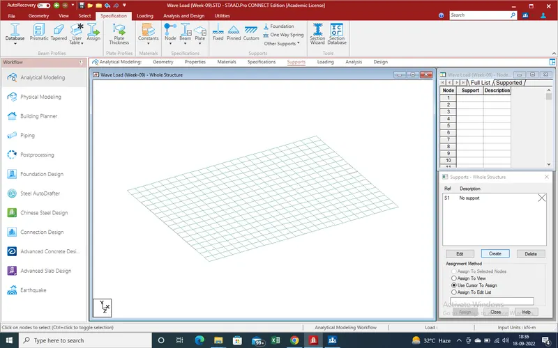
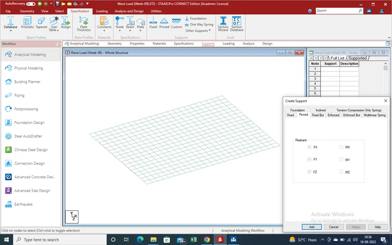
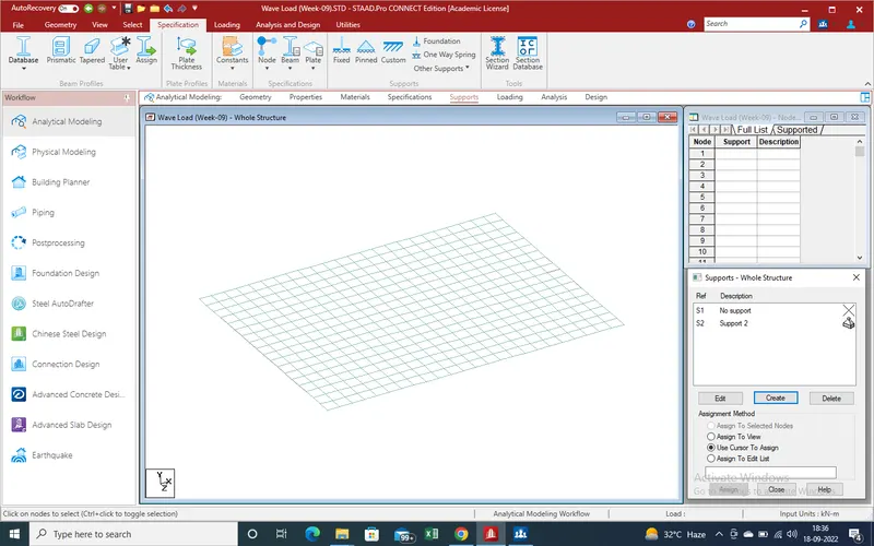
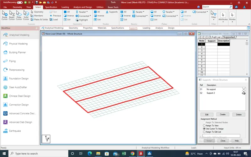
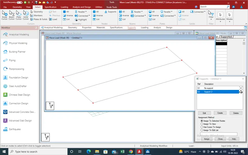
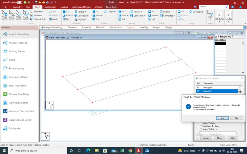
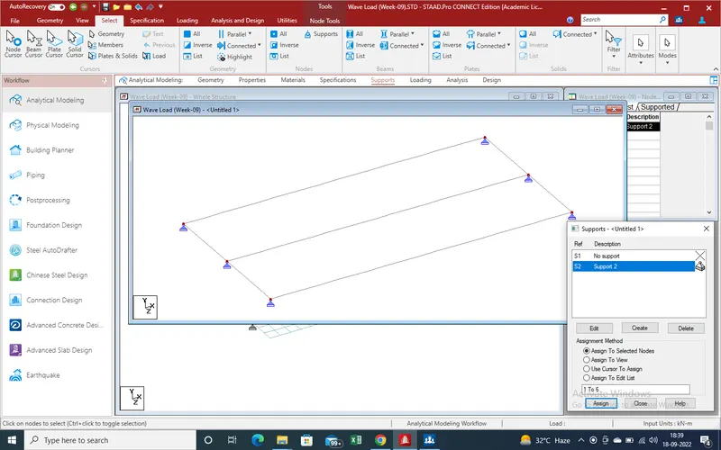
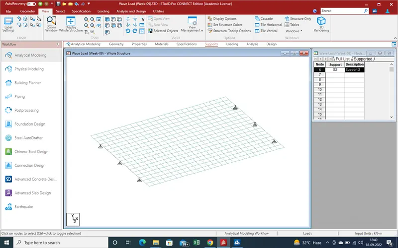
14.Modeling has been created ,now need to apply load apply on bridge as given steps
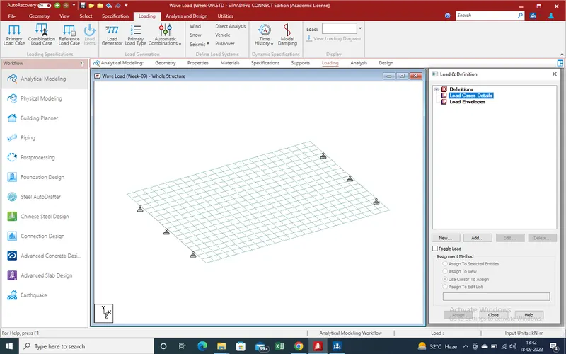
15.Go to load case details "Add" a new window has been open "create the load case " as wave load (vetical ) and add
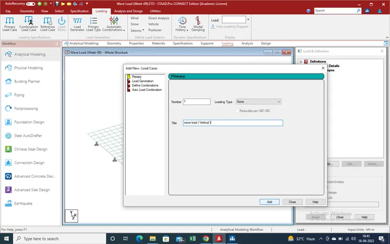
16. Same as create load horizontal loading for wave load .
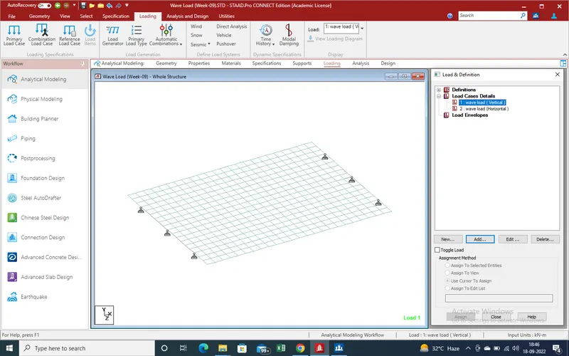
17 . Now again select the vertical load and select the "add" a new widow has been open .
Select the Nodel load as showing a new window showing
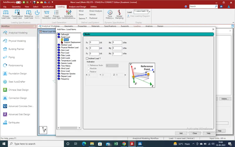
18. Put the value as we perviously define as define in starting modeling
vertical load values are such as 250 kn as nodel load
so put the values in + for direction upward direction
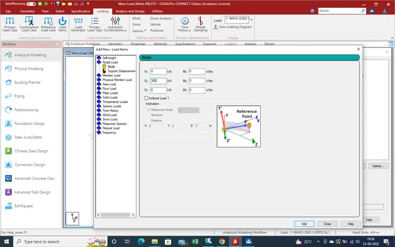
19.Now define horizontal load as nodal load
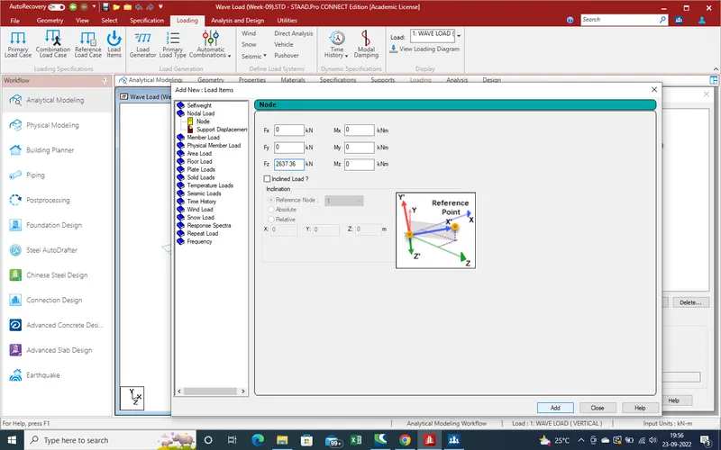
20.Both horizontal and vertical load define ,Now we assign the load on bridge
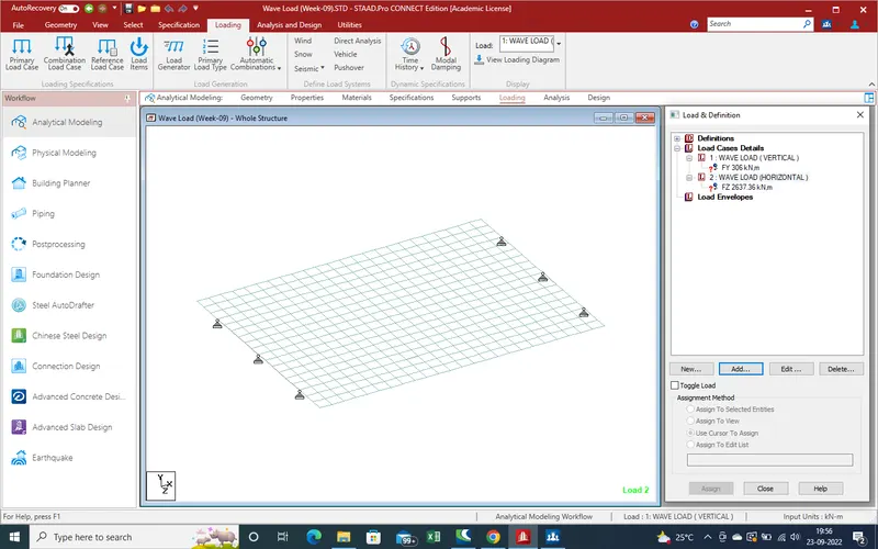
21. Select the main Girder with the help of Beam Selection .
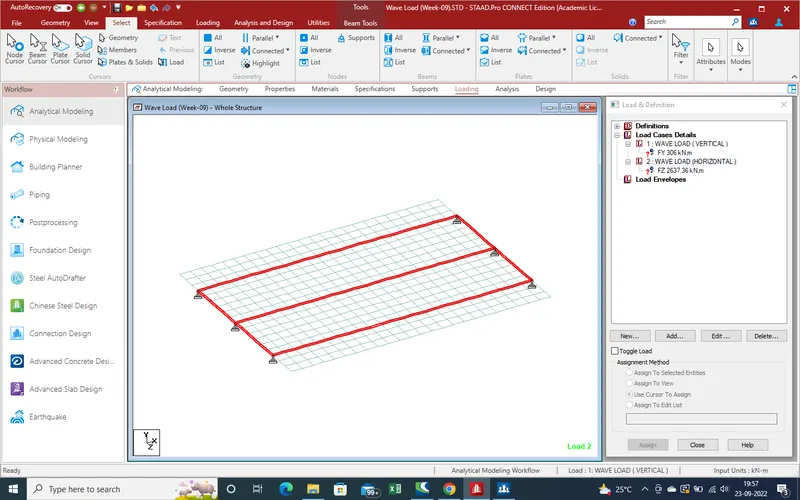
22.Now in new view Select the Main girder .Select the middle node of Beam for apply the load.
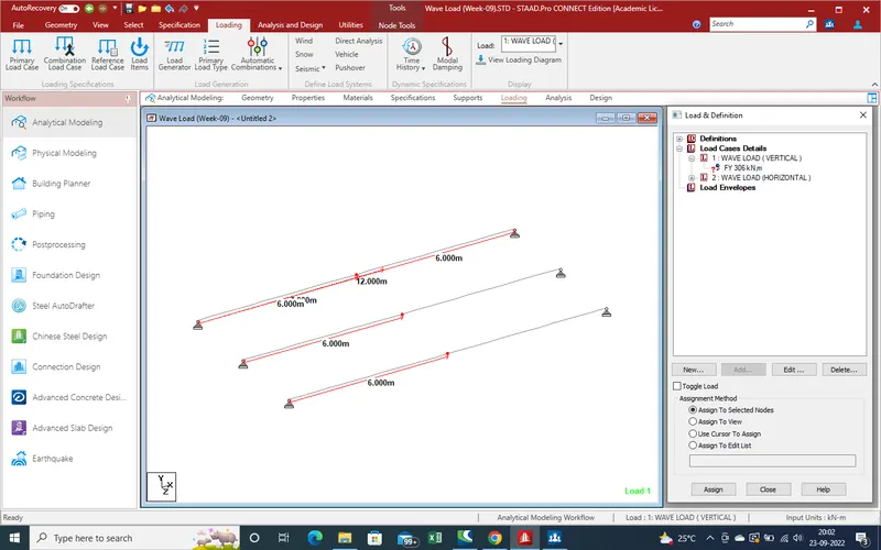
23.Now Select the node and Assign the loading .
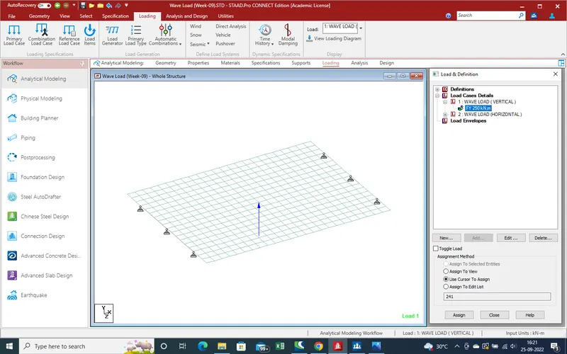
24.Now horizontal Node select for apply load .
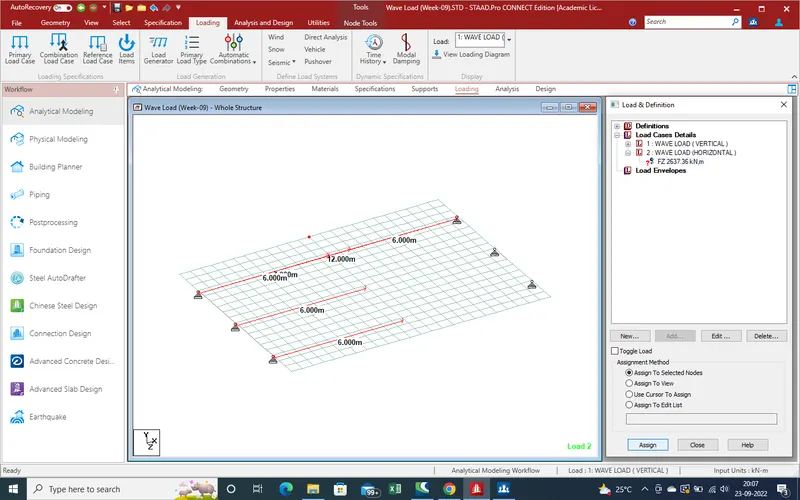
25.Assign the load
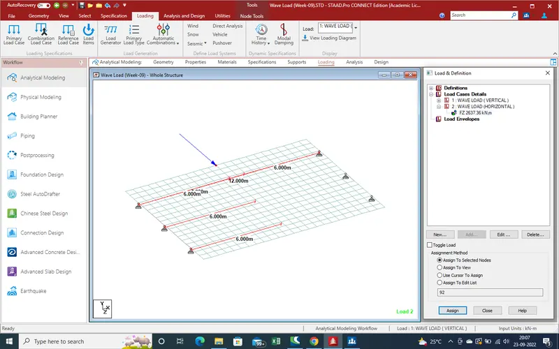
26.Now all loading has been define , Now run the analysis
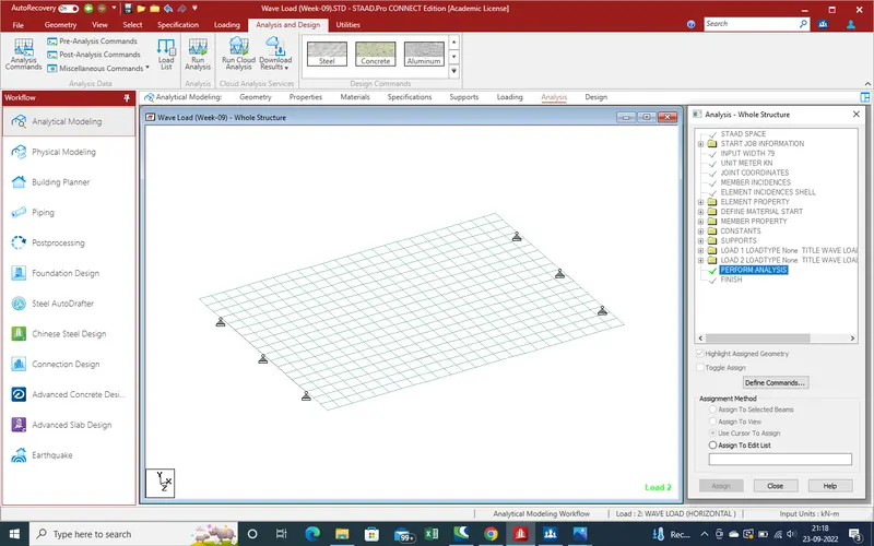
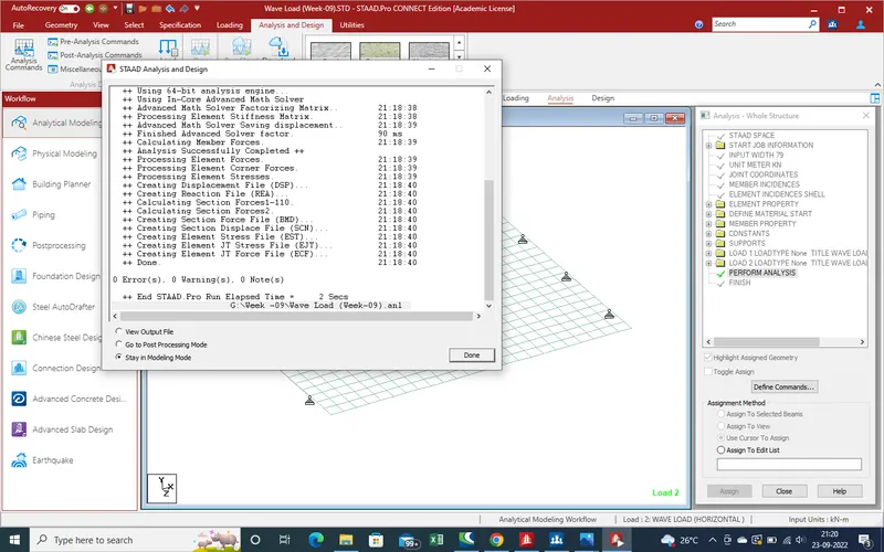
27.After run analysis there is no error in model so , all are ok according to model
28.Now we get the results with the help of given below steps
4.Results :-
1.Now with the help of stadd pro we get the displacement in all direction and Monents ,support reaction and etc .
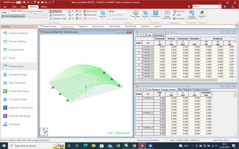
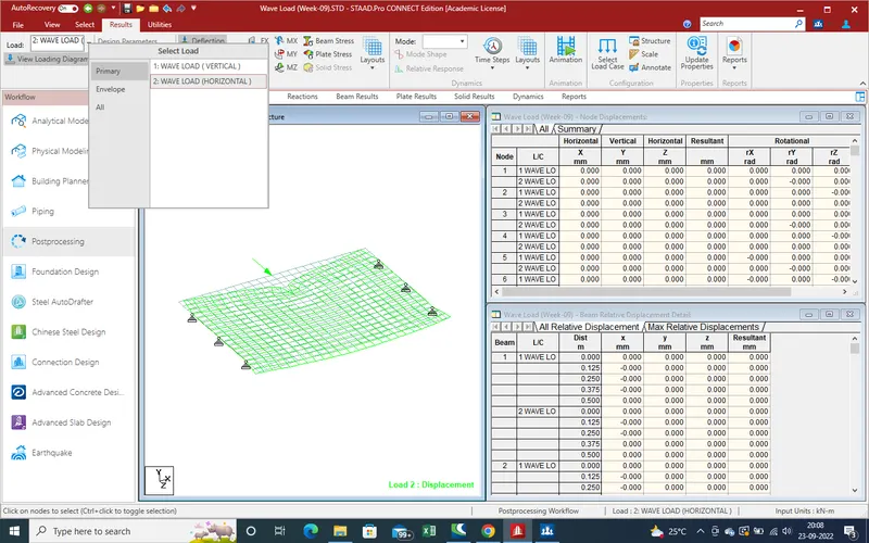
1.When we atcive post processing mode we get the two type load due to wave load which are showing are such as
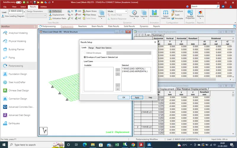
2.Displacement due to vertical load of wave below the girder .
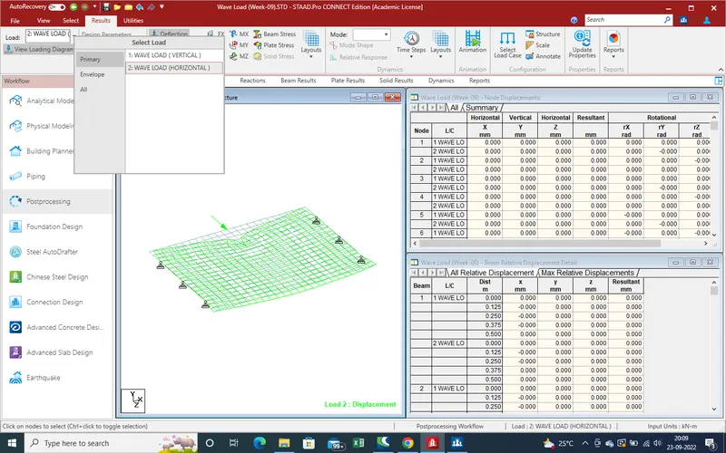
3.Displacement due to horizontal load .
4.
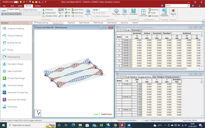
5.Displacement due to horizontal load in X-direction .
6.Shear Force displacement due to vertical Wave load .
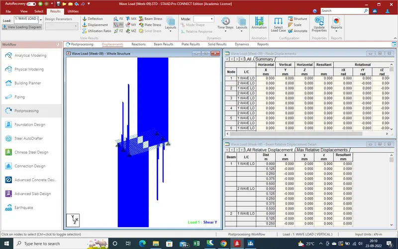
7.Moment Displacement due to vertical wave load .
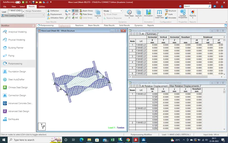
8.Moment Displacement due to Moment Force about Y-direction
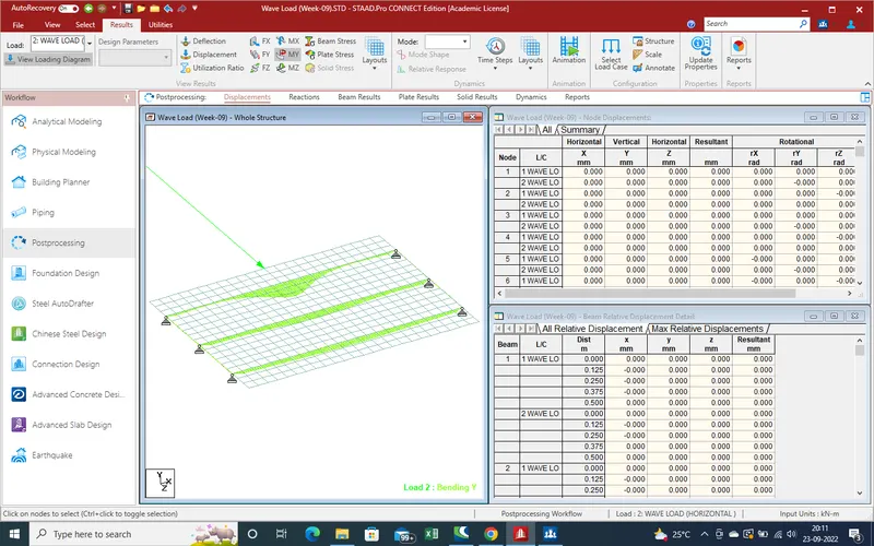
9.Moment displacement due to moment force due to vertical wave load .
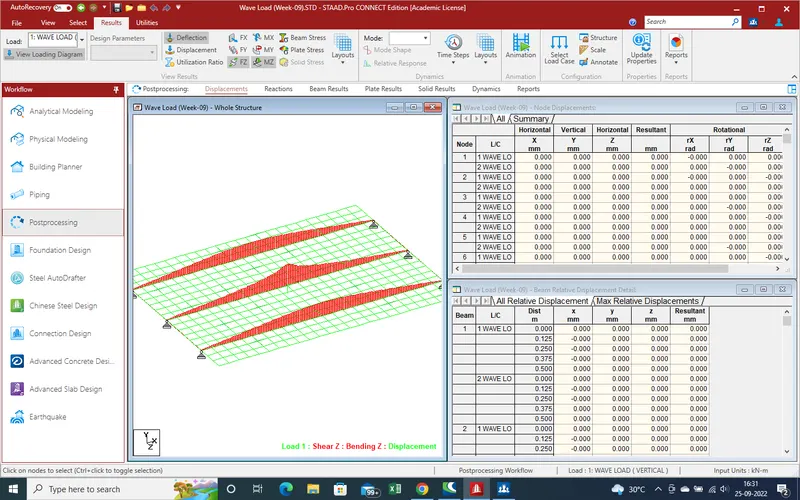
10.Support reaction due to horizontal load .
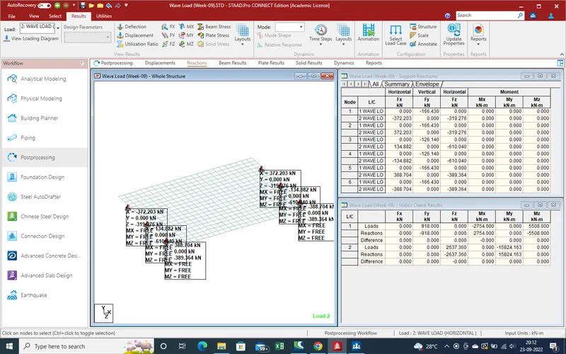
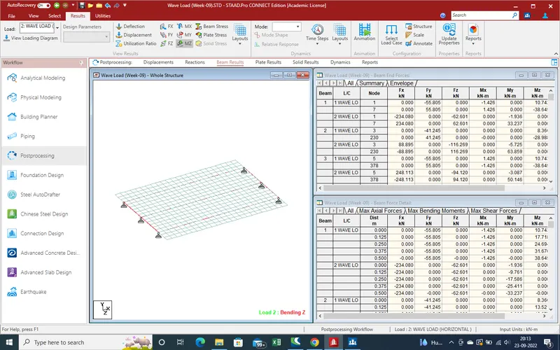
11.Moment results due to moment force due to horizontal load
12.Plates results .
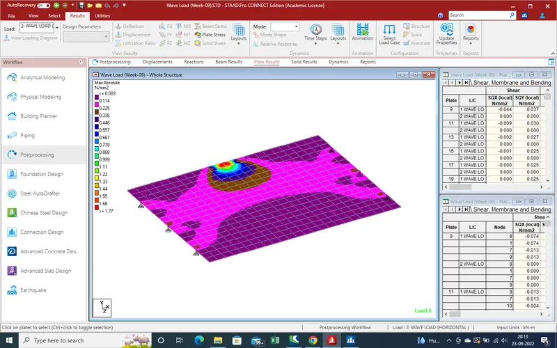
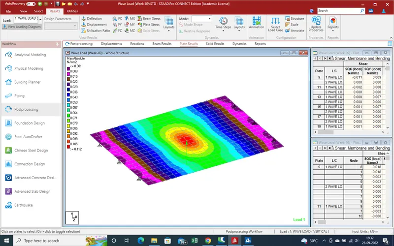
13.Plates results due to vertical wave load on deck slab.
14.Reports for print or Pdf formate .
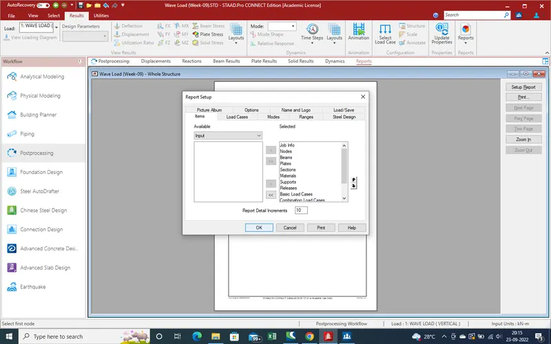
15.Displacement report with high to low displacement
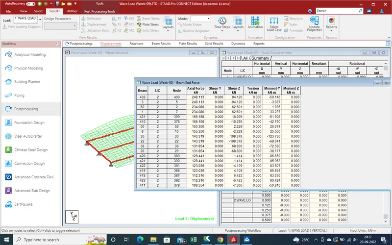
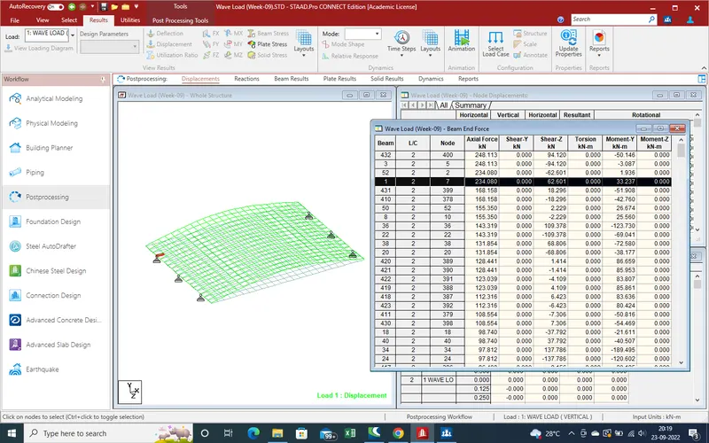
16.Beam results as End
Remark :-
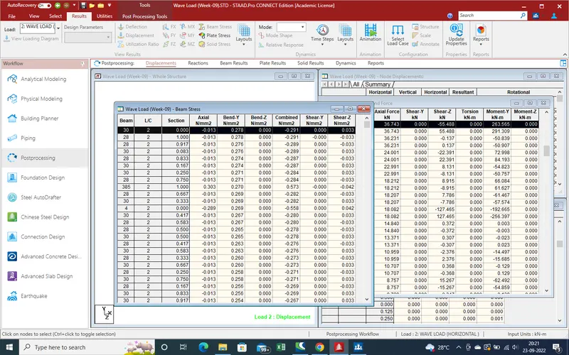
Now we can find results due to wave load on bridge .
1.Here Report and Model both are attached.