Week 9 Challenge
1)
Aim: To design a 3-hinged pitched roof frame for a steel building.
Given:
Assume no wind load acting on the walls and roof. Analyze the frame structure and draw bending moment, shear force, and axial force diagrams of the frame.
The slope of the roof is 1 in 10 and the roof is accessible for maintenance purposes (assume 75 kg/m2) only.
Dead loads on the roof are given below. Assume bay spacing as 5 m and the frame width is 20 m. (Design code as per AISC:ASD. No seismic load consideration is required)
Weight of roofing sheet = 5kg/m2
Weight of purlins + tertiary members = 25 kg/m2
Let us assume the height of the column = 5 m.
Procedure:
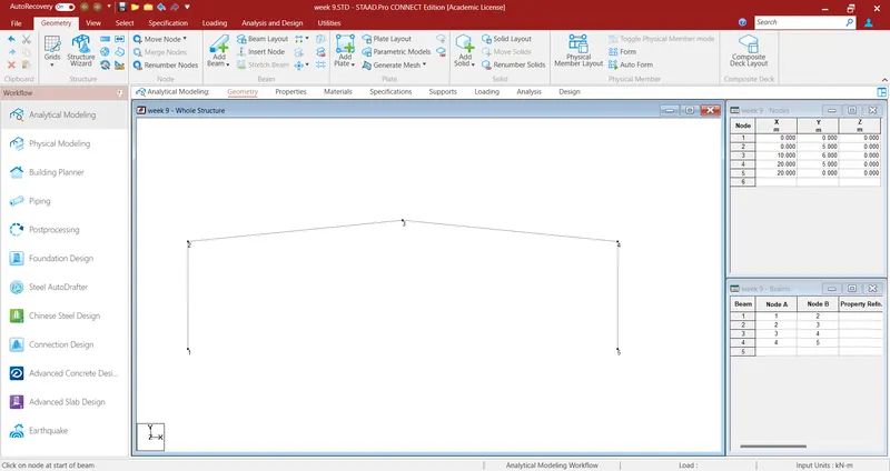
Step 1: Open a new Staad file. Make the basic geometry of the roof frame by firstly creating nodes at correct coordinates and then adding beams between them.
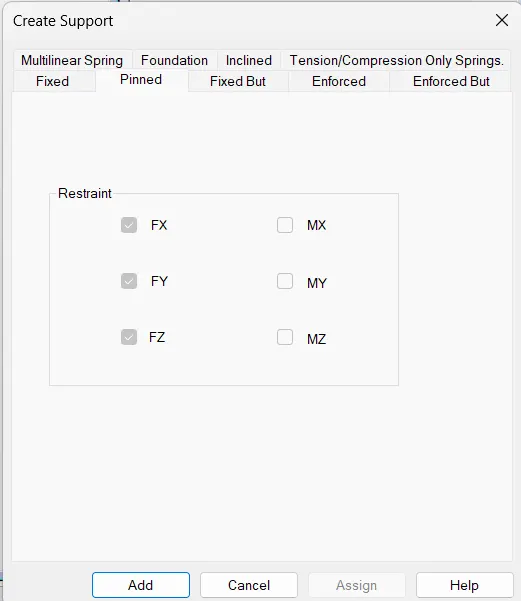
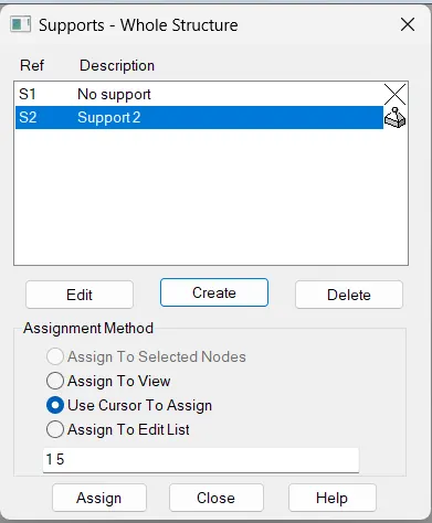
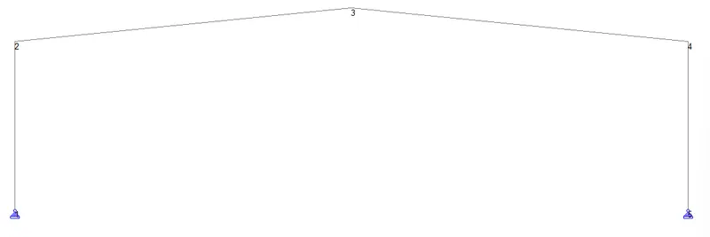
Step 2: Now, add pinned supports to columns. Go to the Support Tab, and click on create to add pinned support.
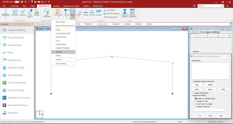
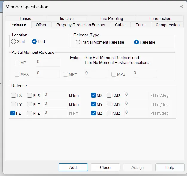
Step 3: Now, add an internal hinge at the joints of the roof, this can be done by adding Moment Release in the frame.
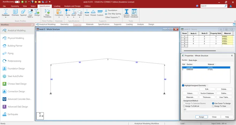
Step 4: Assign the Section property to the Columns and rafter. We have allotted ISMB 500 to Columns and ISMB 300 to Rafters.
Step 5: Now, as per the given data:
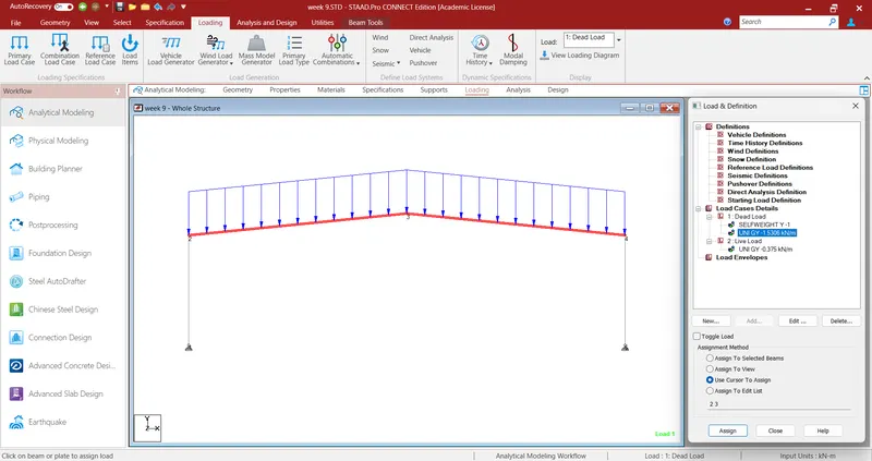
Dead Load = (Self Weight) + Weight of Purlin + Weight of tertiary members + Weight of Roofing Sheets
Total Dead Load = Self Weight + [(25+ 5) (kg)/m2 x 5 m] = 150 (kg)/m = Self Weight + 1.5306 kN/m
Live Load = [75 (kg)/m^2 x 5 m] = 375 kg/m = 0.375 kN
Now, apply the load on the roof frame.
Step 6: Now, run the analysis to create Shear Force Diagram, Bending Moment Diagram, and Axial Force Diagram.
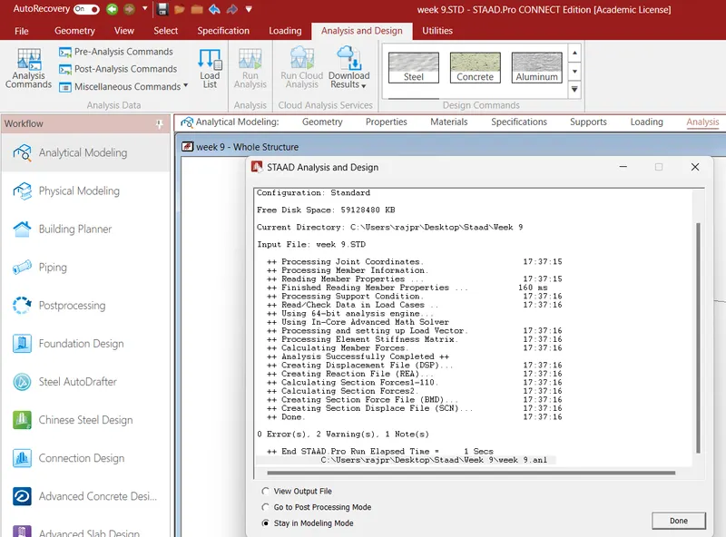
Shear Force Diagram
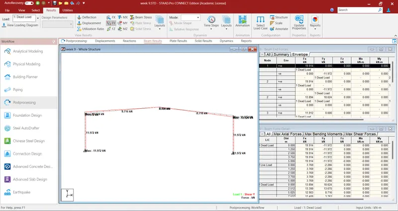
Bending Moment Diagram
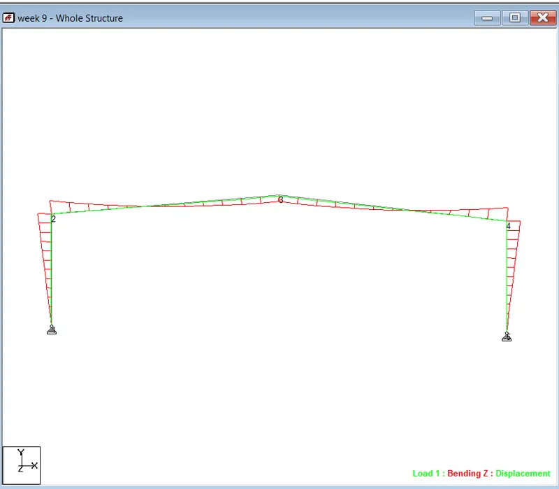
Axial Force Diagram
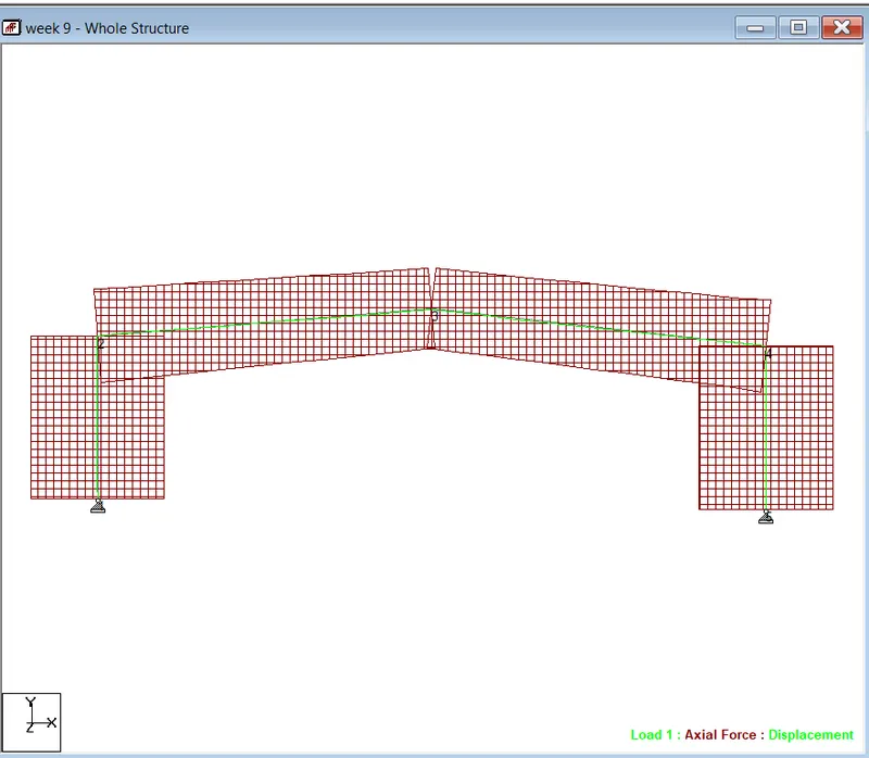
Result: Bending Moment Diagram, Shear Force Diagram, and Axial Force Diagram are obtained successfully.
2)
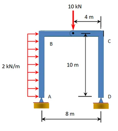
Aim: To draw Bending Moment Diagram for the following cases:
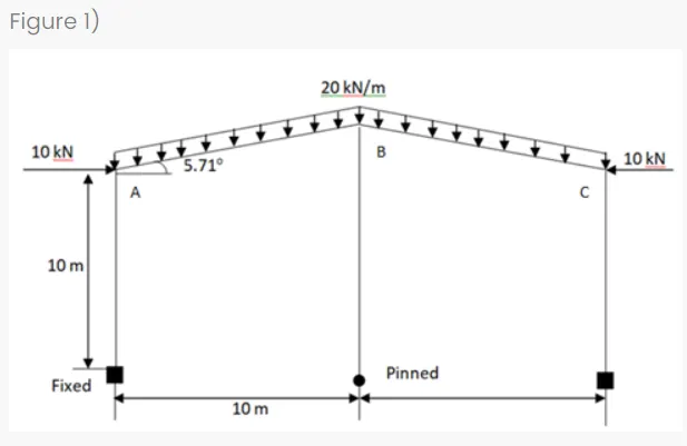
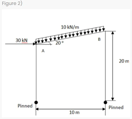
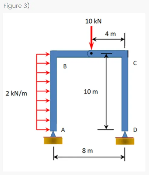
Procedure:
Step 1: Open a new staad file and draw the basic frame structure using nodes and then add beams between them, use the concept of Moment Release to add an internal hinge in between the beams.
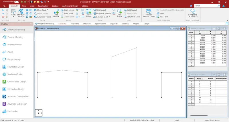
Step 2: Now add supports and an internal hinge as mentioned in the question.
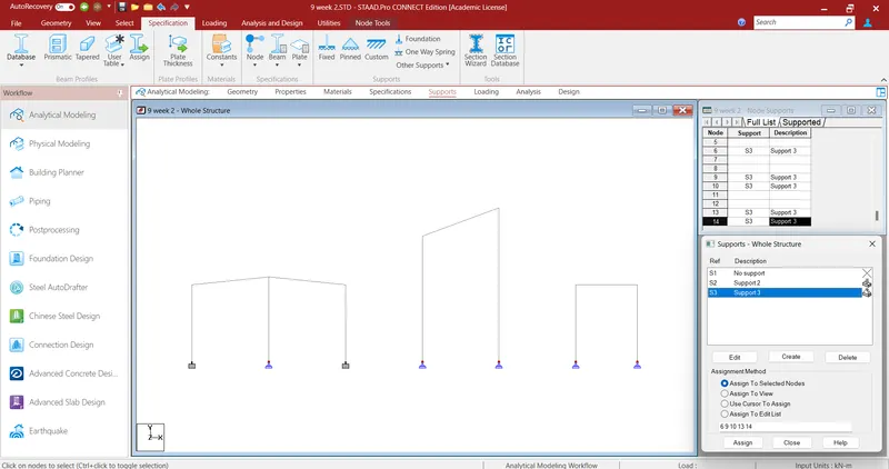
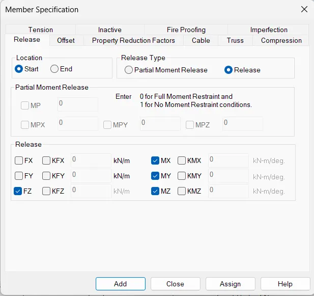
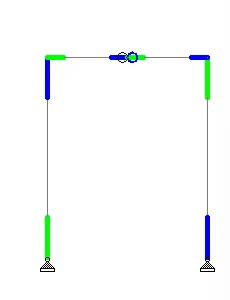
Step 3: Now apply load cases.
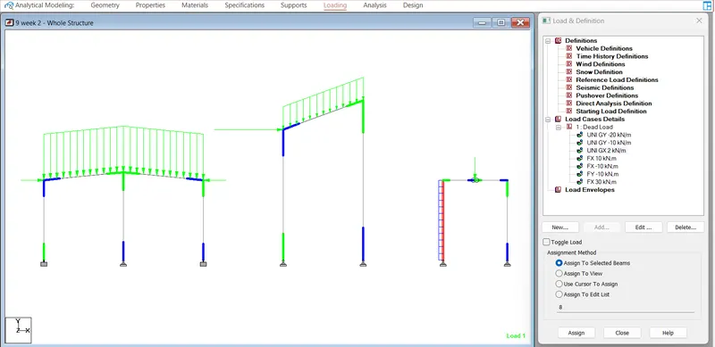
Step 4: Now assign section properties.
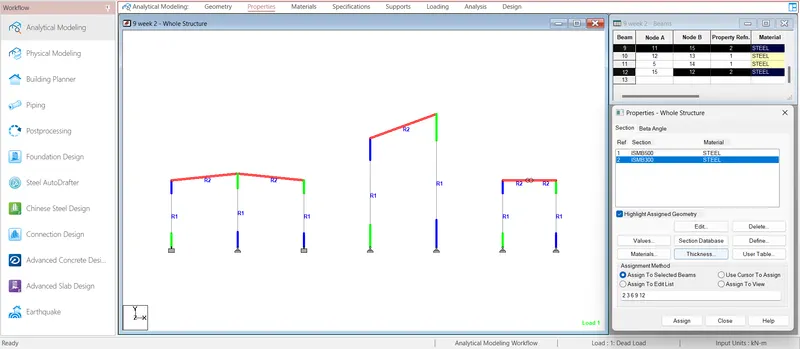
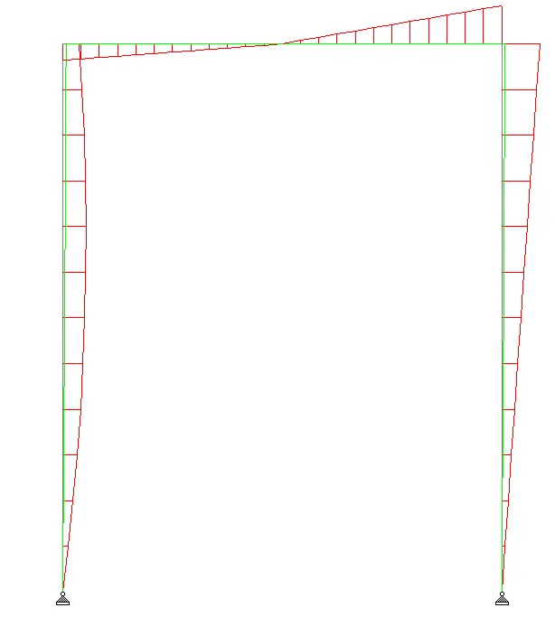
Step 5: Run the analysis and create Bending moment diagram.
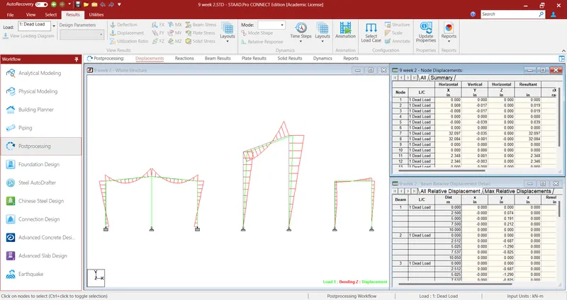
Result: Bending Moment diagrams are drawn in staad pro.
Figure 1)
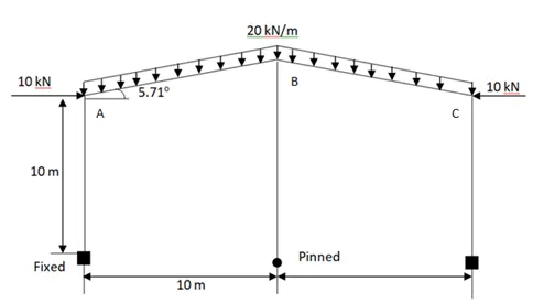
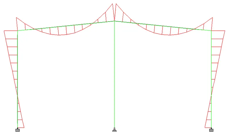
Figure 2)
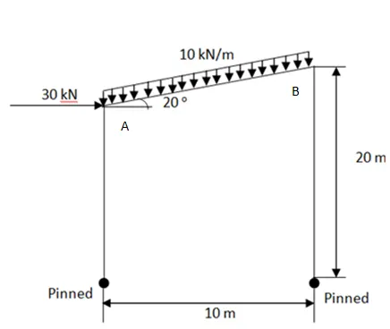
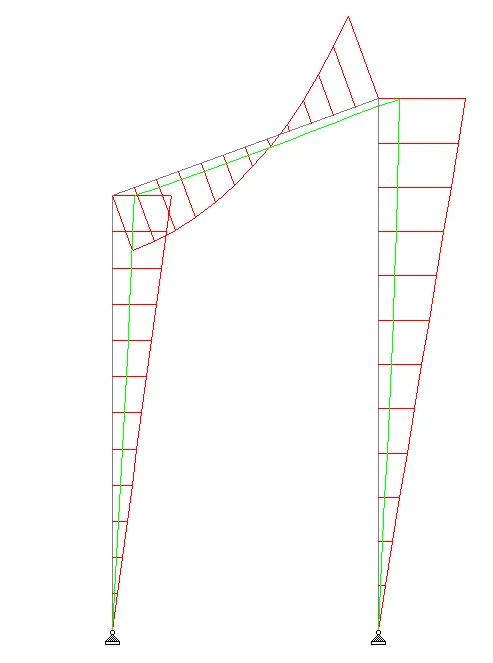
Figure 3)
3)
Aim: To determine the followings:
- Determine the lateral deflection at point A & Vertical deflection at the mid section of the beam between B & C from Figure 1 in the previous challenge.
- Determine the lateral deflection at point A & Vertical deflection at the mid section of the beam between A & B from Figure 2 in the previous challenge.
- Determine the lateral deflection at point A & point B from Figure 3 in the previous challenge.
Procedure:
Step 1: After Running Analysis. Go to the post-processing tab and click on Deflection to view deflection.
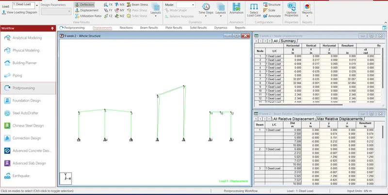
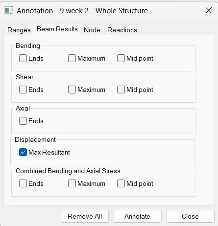
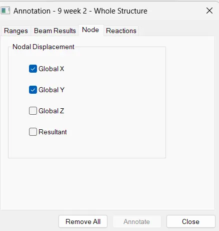
Step 2: Click Annotate option from the tab to display values at Node points.
Result:
For Figure 01
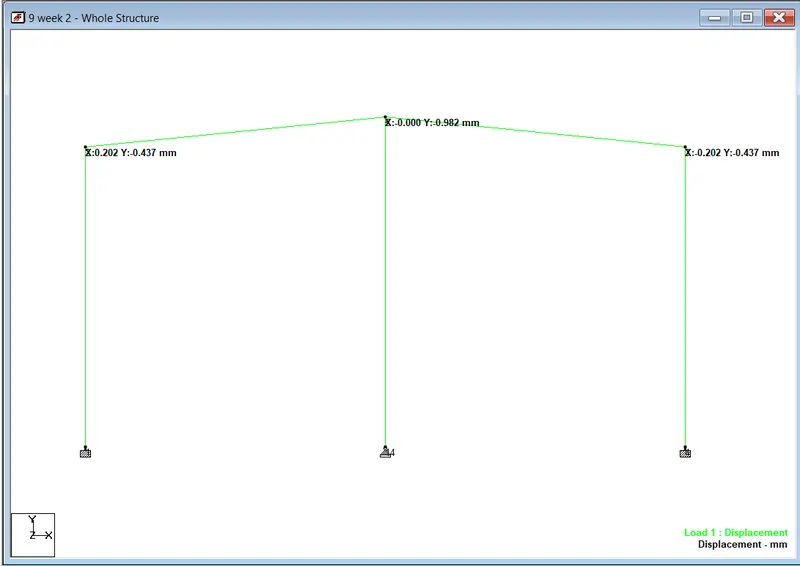
Lateral Displaccement of A = 0.202mm
Vertical Displacement of B = -0.982 mm
Vertical Displacement of C = -0.437 mm
For Figure 02
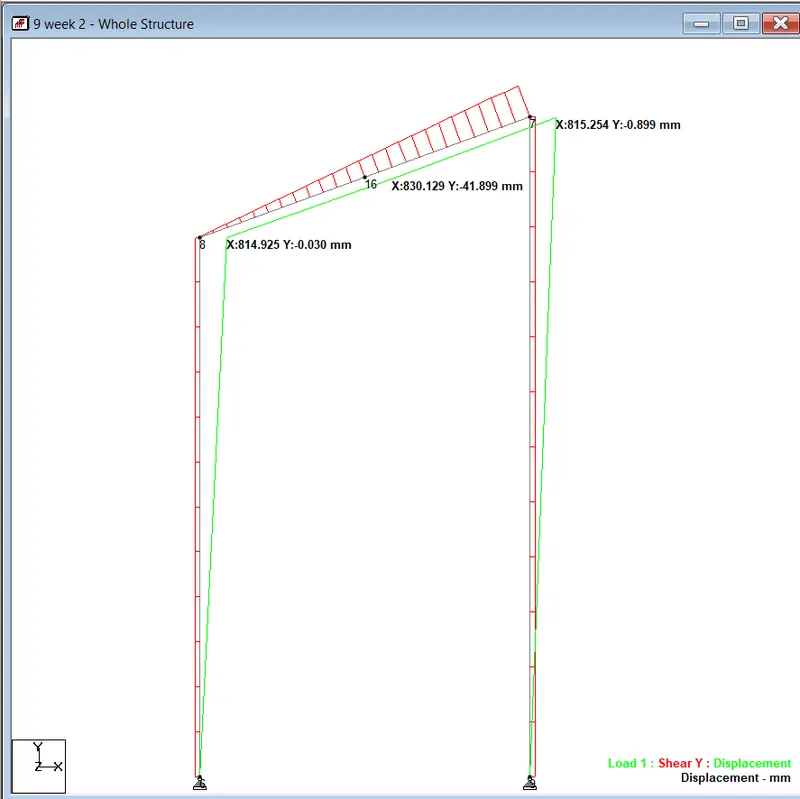
Lateral Deflection of Point A = 814.925 mm
Vertical deflection at the mid-section of the beam A and B = -41.899 mm.
For Figure 03
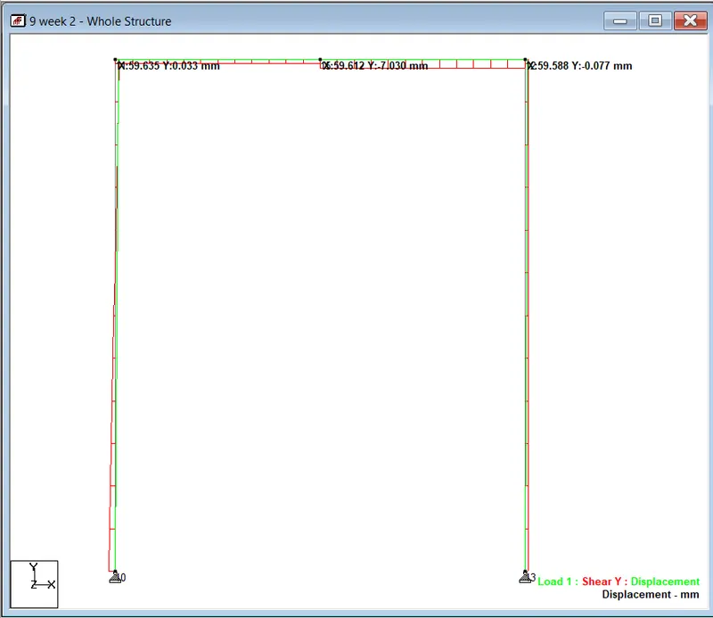
Lateral Deflection of Point A = 59.635 mm
Lateral Deflection of Point B = 59.588 mm.