Week 9 Challenge
1)
AIM:
To design a 3 hinged pitched roof frame of a steel building.
PROCEDURE :
- Open a new Staad file.
- Make the outline of the roof frame by creating nodes at coordinates respective to the give lengths and then add beams connecting them.
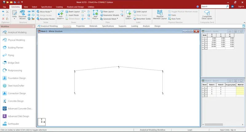
- Now, add pinned supports to columns at the bottoms.
- Go to Supports tab, click on create to add pinned support.
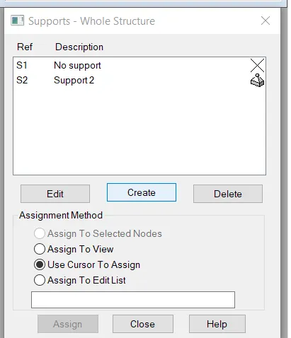
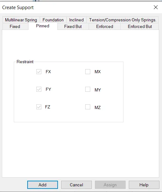
- Create the pinned support and click on add.
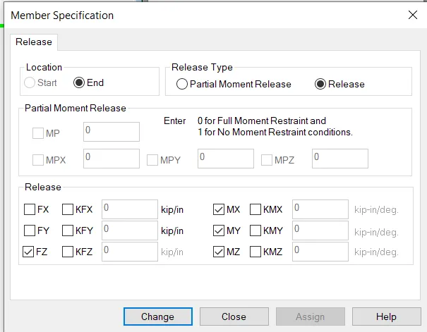
- Now, add internal hinges at the joints of the roof, this can be done by clicking on Moment release in the frame.
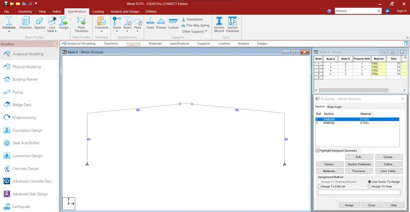
- Now, assign the Section property to the Columns and rafter. I have alloted ISMB 500 to Columns and ISMB 300 to Rafters.
- Now, as per the given data:
-
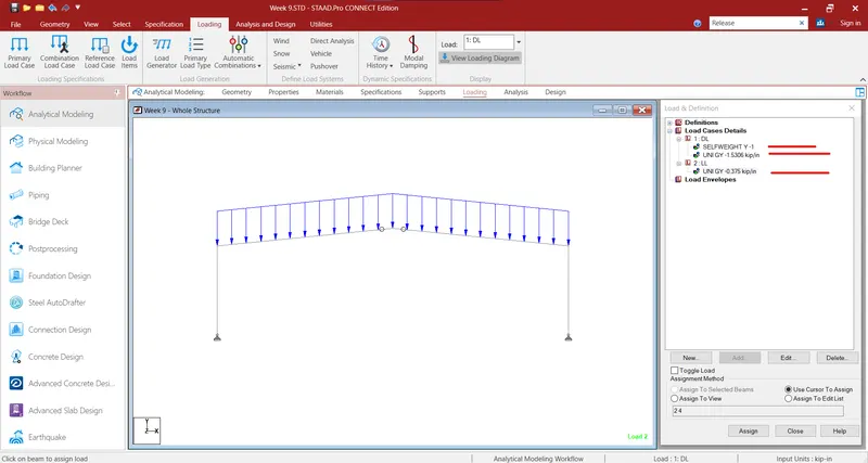
Dead Load = Self Weight + Weight of Purlin + Weight of tertiary members + Weight of Roofing Sheets
Total Dead Load = Self Weight + [(25+ 5) `(kg)/m^2` x 5 m] = 150 `(kg)/m` = Self Weight + 1.5306 kN/m
Live Load = [75 `(kg)/m^2` x 5 m] = 375 kg/m = 0.375 kN
- Apply the load on the roof frame.
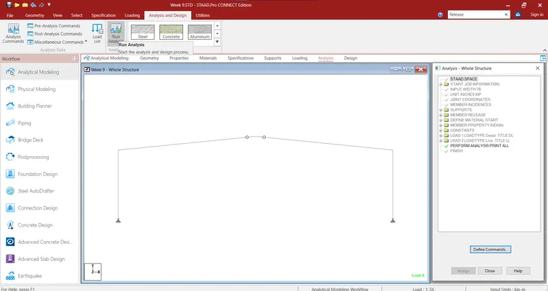
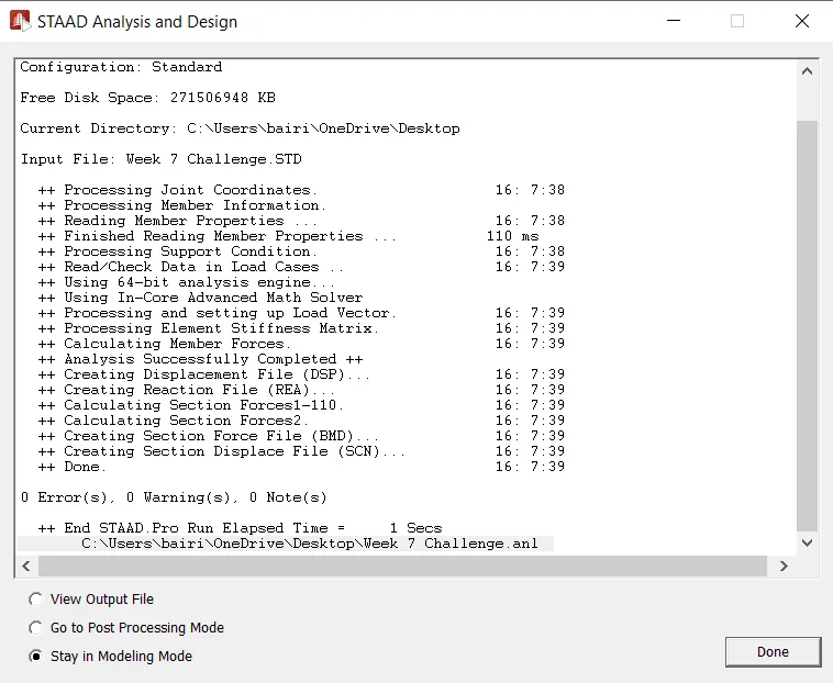
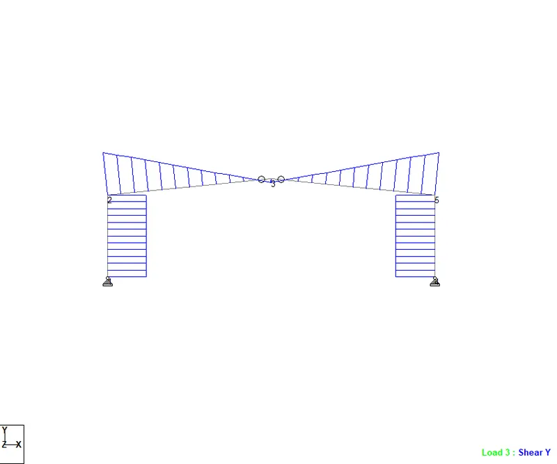
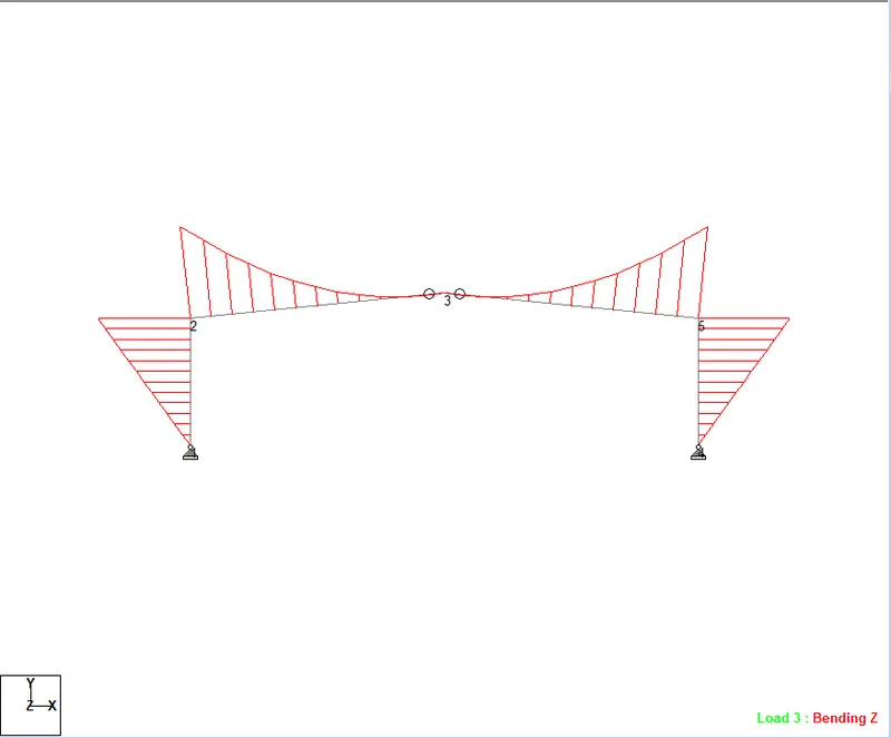
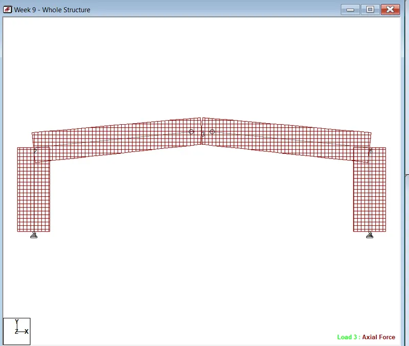
- Do the analysis to create Shear Force Diagram, Bending Moment Diagram and Axial Force Diagram.
Shear Force Diagram:
Bending Moment Diagram:
Axial Force Diagram:
Result:
Bending Moment Diagram, Shear Force Diagram and Axial Force Diagrams of the pitched roof frame are obtained successfully.
2)
Aim:
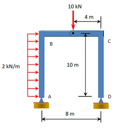
To draw Bending Moment Diagram for the following cases using staad pro:
FIGURE 1 :
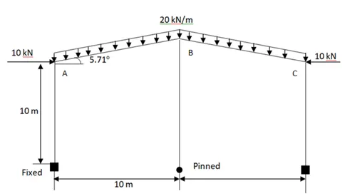
FIGURE 2:
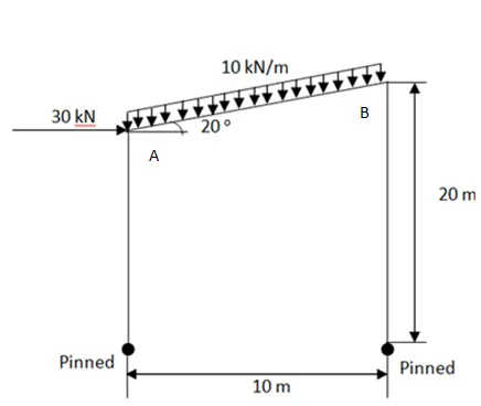
FIGURE 3:
Procedure:
- Open new Staad File.
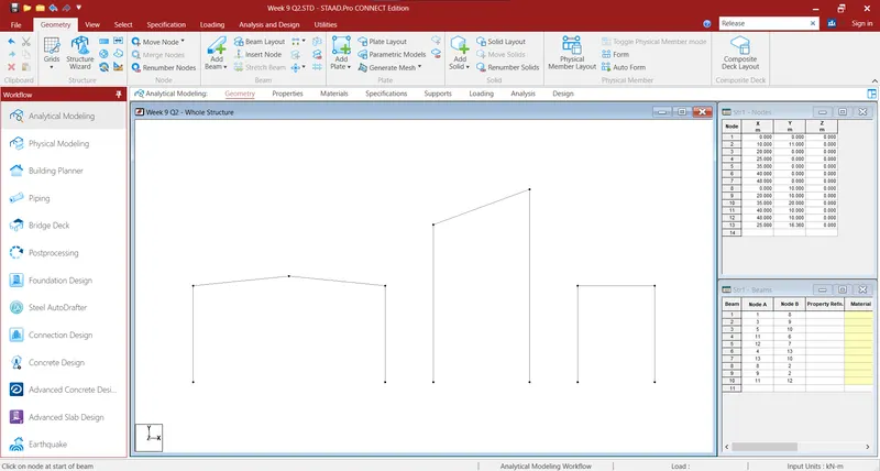
- Draw the basic frame structure creating nodes and then add beams connecting them, use concept of Moment Release to add internal hinge in between the beam.
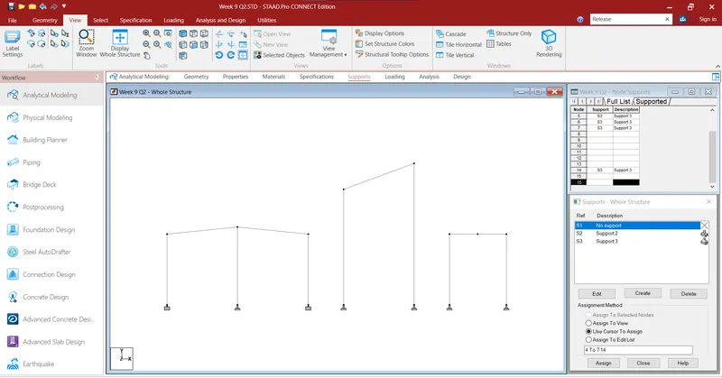
- Now, we will add the supports to the basic frame and internal hinge in the third frame as shown in the figures in the question.
- Now we will apply respective loads on the Frames as given.
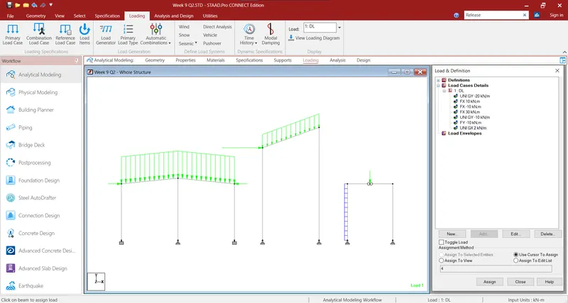
- Now, apply the section properties as we did earlier and run the analysis.
- After running the analysis, Bending Moment Diagram obtained from the post processig mode for the given cases are as shown below.
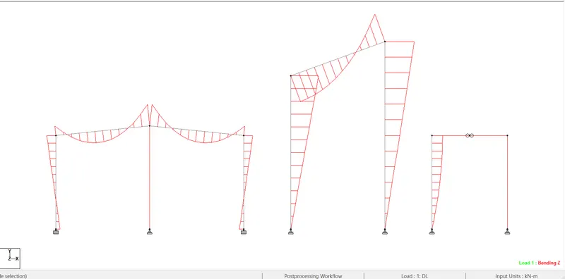
Result:
Bending Moment Diagram for the given following cases has been obtained succcesfully using STAAD.PRO.
3)
Aim:
To determine the following deflections using staad pro:
- Determine the lateral deflection at point A & Vertical deflection at mid section of beam between B & C from Figure 1 in previous challenge.
- Determine the lateral deflection at point A & Vertical deflection at mid section of beam between A & B from Figure 2 in previous challenge.
- Determine the lateral deflection at point A & point B from Figure 3 in previous challenge.
Procedure:
- Open the previous staad file we are working on.
- Continue working on it following the below steps
- After running the analysis, go to post processing mode.
- Click on Deflection to view the deflected shape of the respective frames.
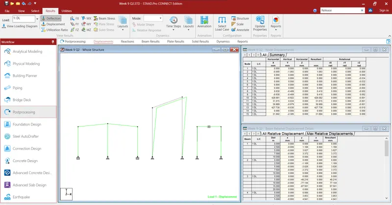
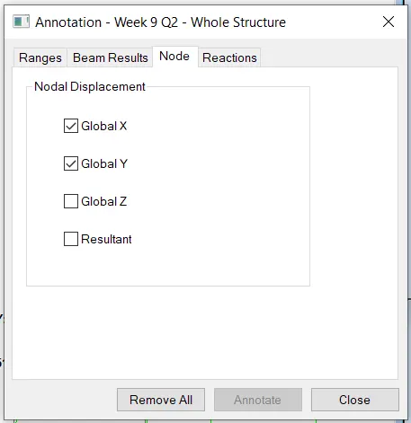
- Go to Annotate option and check the box to view the numerical value of deflection at node points.
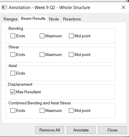
- LATERAL DEFLECTION FOR FIG 1:
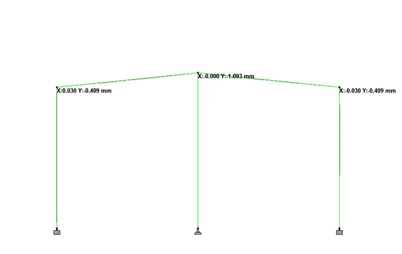
Lateral Displaccement of A = 0.030mm
Vertical Displacement of B = -1.093 mm
Vertical Displacement of C = -0.409 mm
- LATERAL DEFLECTION FOR FIG 2:
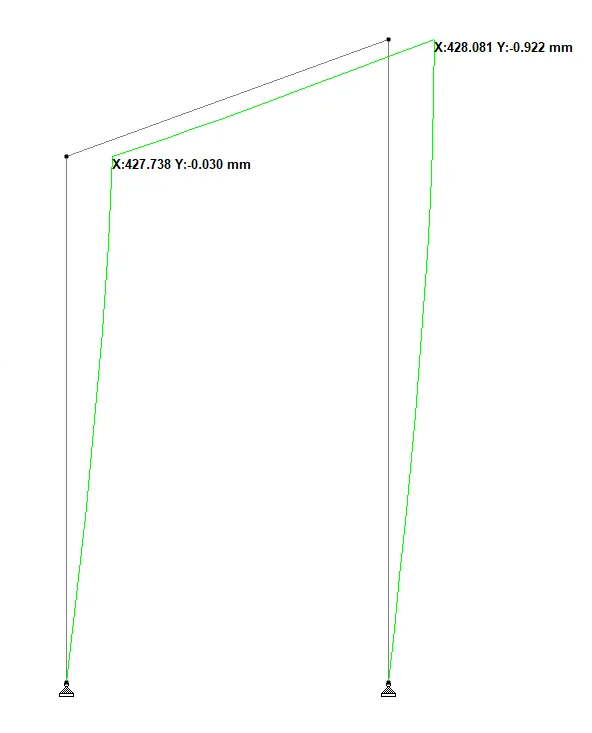
Lateral Deflection of Point A = 427.738 mm
Maximum Deflection of Beam between A and B = 434.366 mm
- LATERAL DEFLECTION FOR FIG 3:
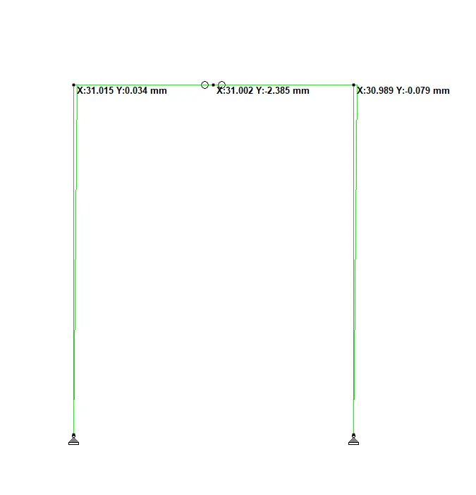
Lateral Deflection of Point A = 31.015 mm
Lateral Deflection of Point B = 30.989 mm.
Result:
Deflection of the points and the beams for the given cases has been obtained successfully.