Week 9 - Challenge 3 - Bumper
AIM :-
To create the Bumper Plastic component from the provided Class-A surface. To begin with, the tooling axis for the given Class-A Surface should be created meeting the requirements of the draft angle take as 3 Degree, and at the end perform the Draft analysis on the model. Take the Thickness of the component to be 3 mm
ABSTRACT :-
Here need to make a first class B surface from provided Class A surface. Then cteation the Class C with And Adding together Class A&C, trim this A+C with Class B surfaces. After got a complete closed surfaced & fianally maked to it Solid one.
PROCEDURE 1st :- To check the Class A surface.
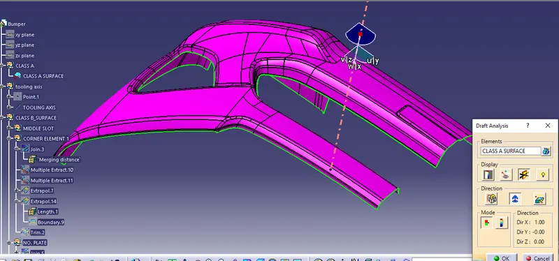
For the creation any plastic component we need to check the provided Class A surface. It is neccesary for the moving forward step for the creation error free component. If any issue is there ask the new Class A component for the design purpose. firstly check the boundry line all over the surfaces & no any patch with in it Here attached a snap that the Class A surface is ok then we move forward to making a component.
PROCEDURE 2 :- TOOLING AXIS
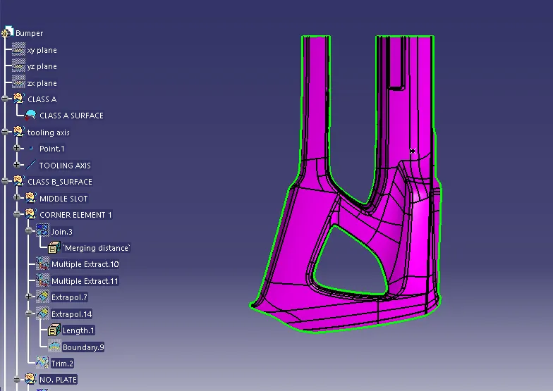
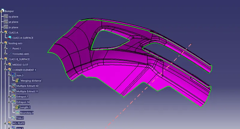
For the creation the tooling axis, the point has to be making. The point has been make on the surfaces, where the axis has also generation should be in component are show all area. Here all are and parts are show with only x direction. so point and line has to becreated in the same x direction.
PROCEDURE 3rd :- CLASS B_SURFACES
The offset is taken from the Class A surface to making the Class B_surfaces, with an 3 mm distance. Because the component thickness limit given as 3mm so.
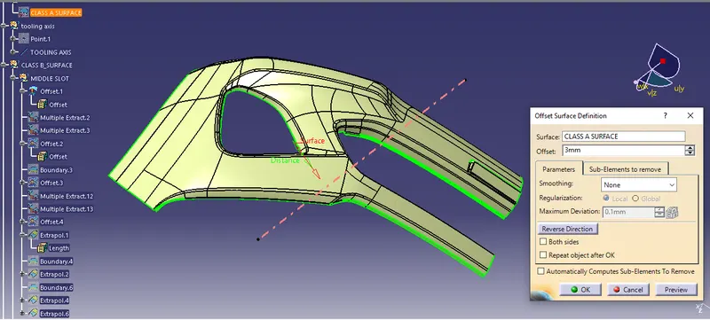
- over the component 3 places has patches are shown as; Iin the middle slot corner, On the side of a Number plate & outer edge.
- After making a offset from the Class A there will be multile patches has shown all over the boundry has checked.
- So to avoid this take a proper multiple extrude there with using add commond .
- The patched area are seperated by the using extrude commond is there, and applyied the extrapolation.
- Finally extrapolated edges/surfaces are to be trim and get a desired unpatched clear boundry is there.
- In this way finally got a Class B surface with providing proper Fillet Radius to the specified corners.
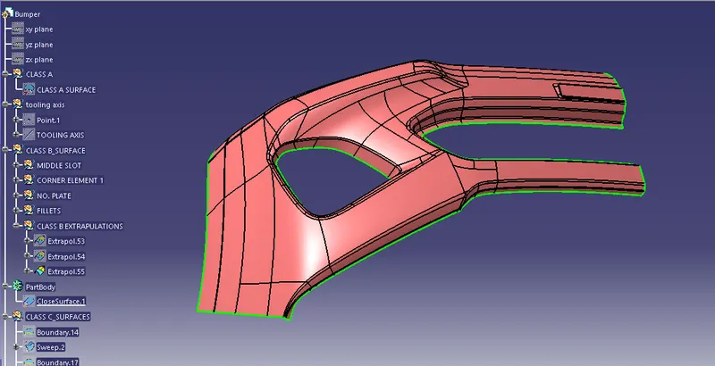
PROCEDURE :- 4th :- Making a Class_C
- For making the class_c the referance has taken from the class_A as well.
- Take a Sweep with the reference surface which are to be parallel to the tooling axis, 90 degree.
- & with Draft direction which are perpendicular to the tooling axis, 3 degree respectively and created such manner Class_C.
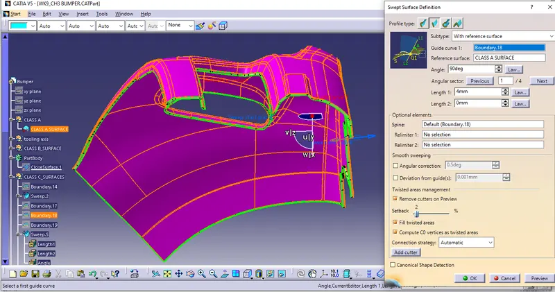
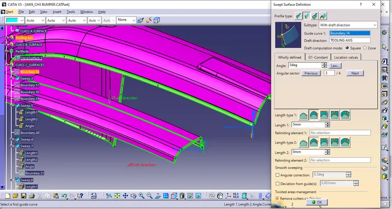
FINAL CLASS_C SURFACE.
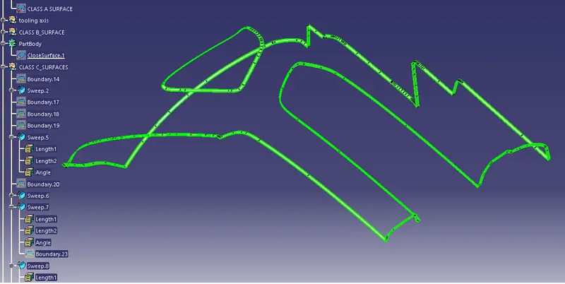
PROCEDURE 5th :- Adding the Class A with the Class_C.
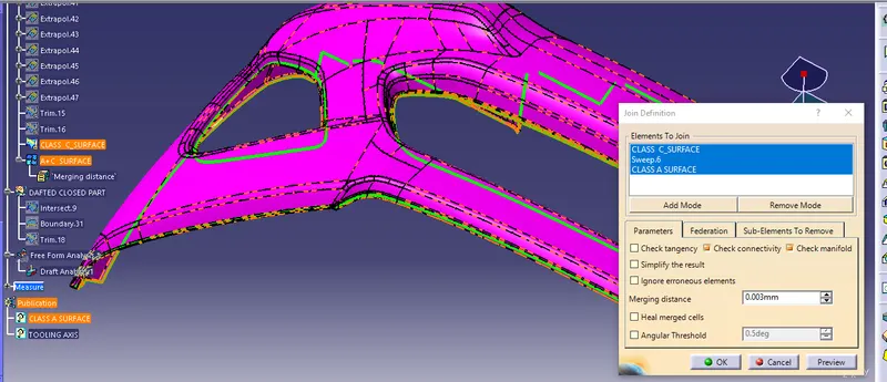
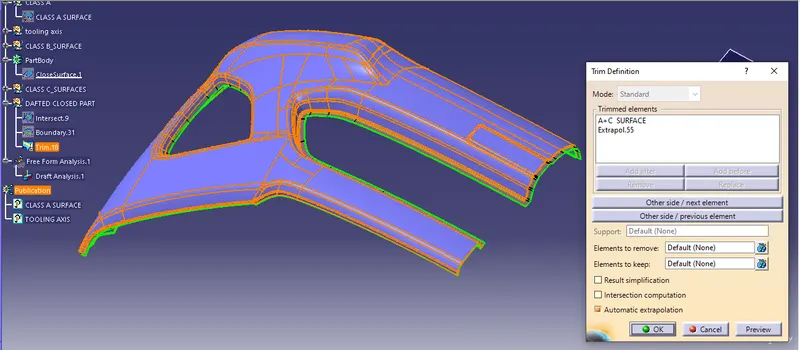
PROCEDURE 6th :- FINAL TRIM// CLOSED SURFACE.
We should take a final trim with the A+C surface and Class C surface.
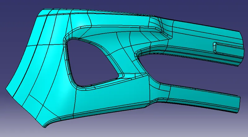
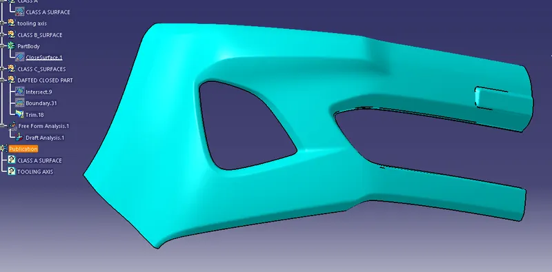
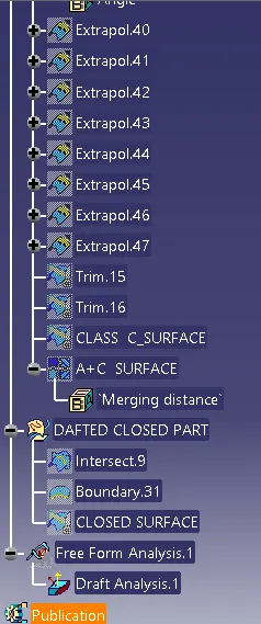
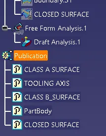
- Proper Geometrical sets & Publications.
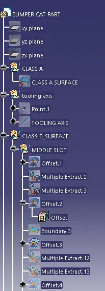
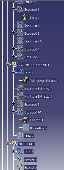
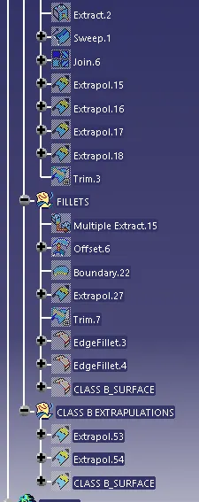
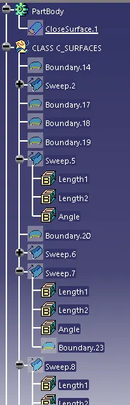
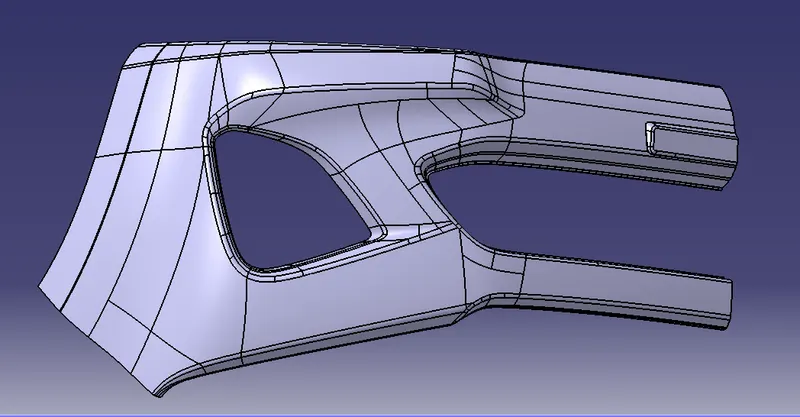
- CLOSED BODY :-
from the closed surface, we should the Generative shape design into the part workbench, and select a commond solid surfaced, and got it a Closed Body.
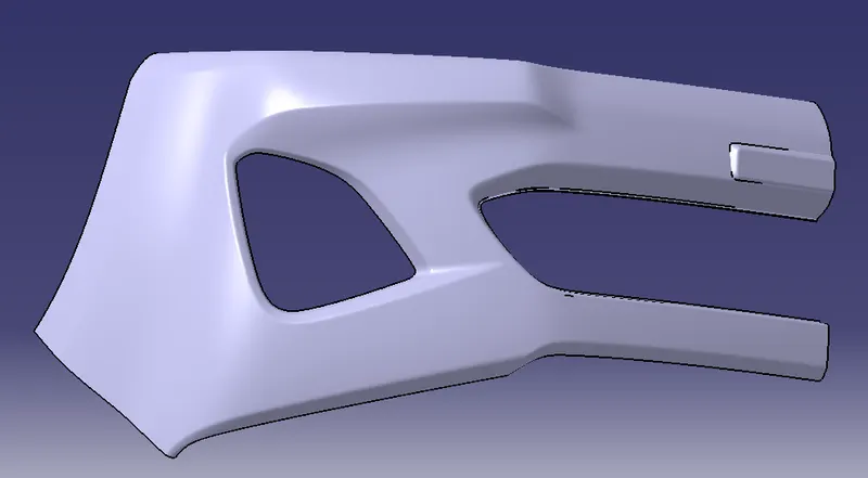
- CLOSED BODY WITH SMOOTH EDGES.
CONCLUSION :-
In this way we have got a closed surface from a simple Class A surface, with an 3 mm tickness provided and angle of draft is 3 mm diamension. Also finally get a closed body. The neccesary snaps are attached to the report with an proper geometrical sets . Cat part file has browse respectively.
Thank You.