Week 9 - Challenge 3 - Bumper
ANSWER
OBJECTIVES
- To develop a tooling strategy.
- To prepare the final close body and conduct draught analysis on a given A-Surface.
- To use the provided Class-A surface to create the B-Surface and C-Surface in order to design the bumper plastic component.
- Take the Thickness of the component to be 3 mm.
INTRODUCTION
The A-class surface is the product designer's contribution. The product designer's task is to design the B and C surfaces while taking into account all of the mould's requirements.
CLASS A SURFACE
- visual appearance and surface.
- textured surface.
- Customer-provided surfaces(OEM).
- On class A surfaces, avoid having any characteristics like ribs, snaps, bosses, etc.
- Class A surfaces are created from scanned data using various software programs, such as alias, etc.
- Class-A surfaces are those with CONTINUOUS CURVATURE.
CLASS B SURFACE
- surface that is observable.
- The majority of surfaces lack textures.
- It is necessary to create surfaces in accordance with class-A surfaces.
- All features (Rib, Boss, Snap, etc.) are only present on the B-side surface.
- Class-B surfaces are those that have TANGENT CONTINUITY.
CLASS A SURFACE CREATION
Check the Class A Surface's connectivity. Using the combine command, make sure there are no gaps between the components. We can visually inspect it or use the boundary command to do so. It has outer limits. So, the initial check is finished.
PROCEDURE
TOOLING AXIS DIRECTION
- For both plastic parts and mould parts, tooling orientation is crucial because it determines how mould parts move and whether plastic parts can emerge from mould parts. (Core and Cavity).
- An arrangement is made in a moulding machine to release the mould in a direction known as the tooling direction
- Alternatively, put. The mould is constructed of two distinct halves (the Core and Cavity), and the tooling orientation essentially determines which way the mould pulls apart.
- The main direction is the direction of the tool.
PREPARATION OF TOOLING DIRECTION
The tooling direction is being created on the specified class A surface. Select the best base and side walls, then draw the axis-pointing line. I used the Center of Gravity as a guide when choosing the tooling orientation. which aids in locating the centre point and enables us to draw a line using a point and a flat surface. Consequently, we think about the final tooling direction.
SURFACE B CREATION
Is created with help of A-Surface by using the Off-set,Trim command,Multi Section,Sweep and Fill command.
SURFACE C CREATION
is produced with the aid of A-Surface and the commands Sweep and Boundary.
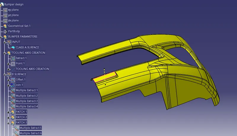
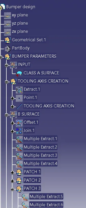
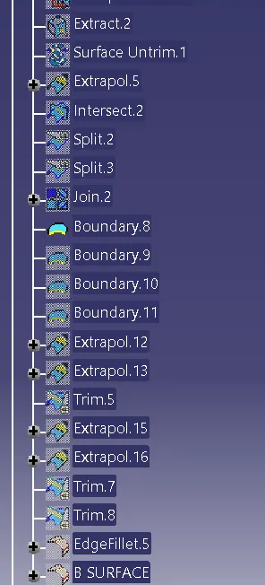
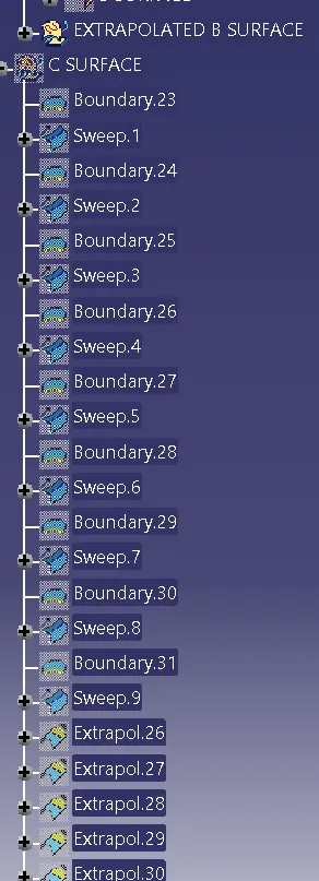
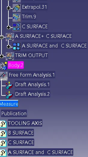
TREE STRUCTURE