Week 9 - Challenge 3 - Bumper
Bumper-
Design technique followed for creation of the bumper
*) Design was started by initially checking the quality of class A surface. The same surface was used to create the boundary by selecting boundary definition.
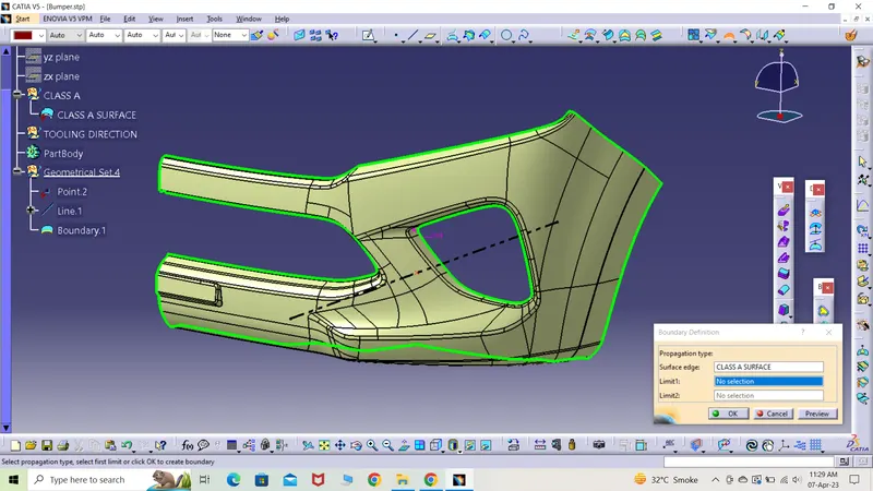
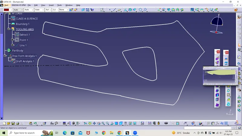
*) The boundary was continous and had no weird lines or curved in odd locations so the class A surface was good to go for creation.
*) The next step was to create the tooling direction. There are two methods to create tooling axis 1)Extracting the flat region, 2)Measure inertia.
*) Measure inertia method cannot be used as it gave a tooling axis somewhere near the side of the bumper which is not acceptable as the given bumper is a half part. The tooling axis should be somewhere at the center of the complete part.
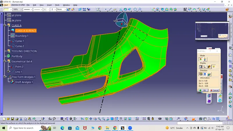
*) The surface was looked all the three planes and the maximum surface was visible only in yz plane.
view in all the different planes i.e. xz,xy,yz planes respectively are shown below.
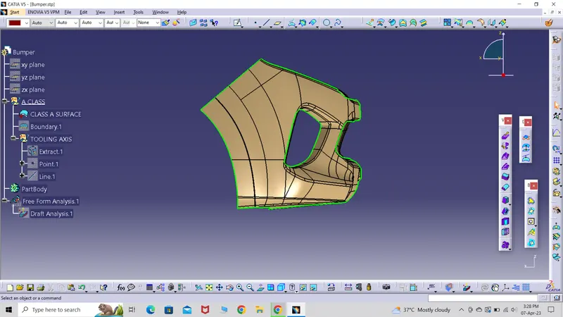
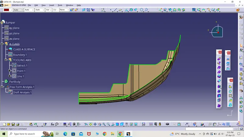
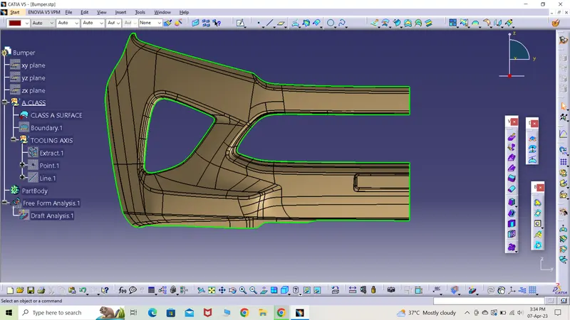
*) For the aforementioned reason, the number plate mounting flange was extracted and a point was created by selecting surface. X-component is selected for the direction of the axis.
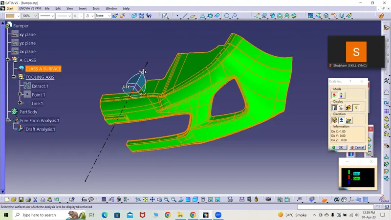
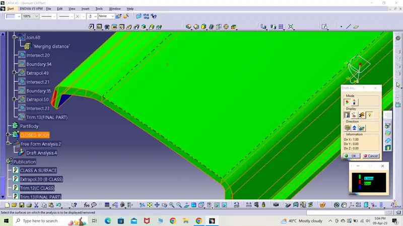
*) The same axis was used to execute draft analysis and the part was observed as toolable and producible by injection moulding process.
*) A new geometrical set is inserted and was named as Class B surface. This set contains all the operations and commands that were used to create the same surface.
*) Class A surface was offsetted to 3mm(offset distance=thickness of the part). It was observed that 95% of the part was offsetted but only the regions with fillets weren't. The simplest option was to measure the fillet radius and add some value to the same and create the fillet.
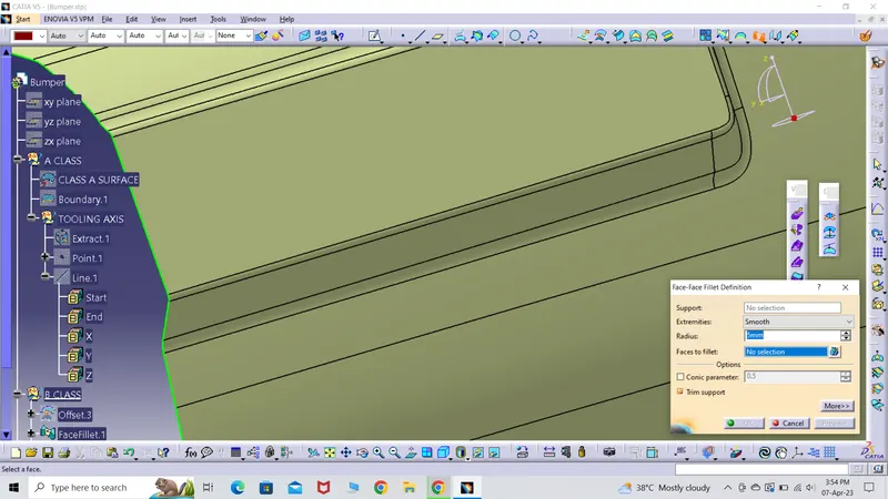
*) But for a plastic design engineer adding or modifying anything in the master file or value would ultimately lead to a wrong design of the part.
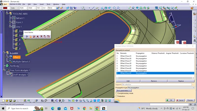
*) By adapting the right approach, the specified flange was multi-extracted.
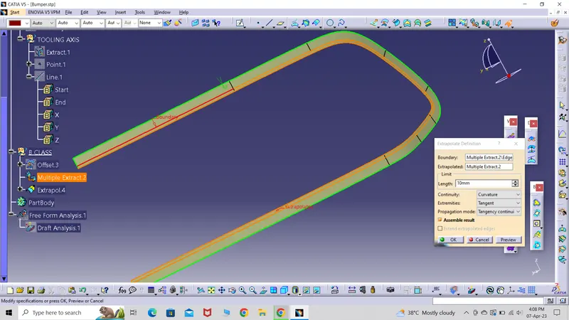
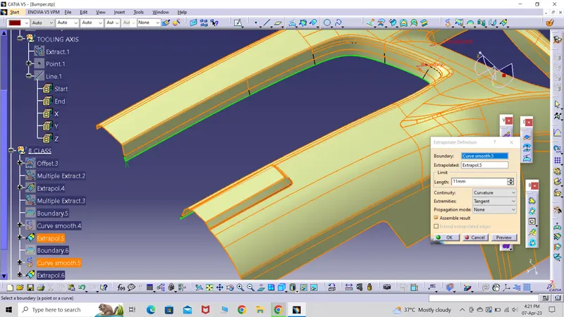
*) The extracted flange was later extrapolated to 10mm and which would be used in the later process.
*) The remaining portion of the bumper was multi-extracted and complementary mode was checked to save time in selected the particular regions on the surfaces.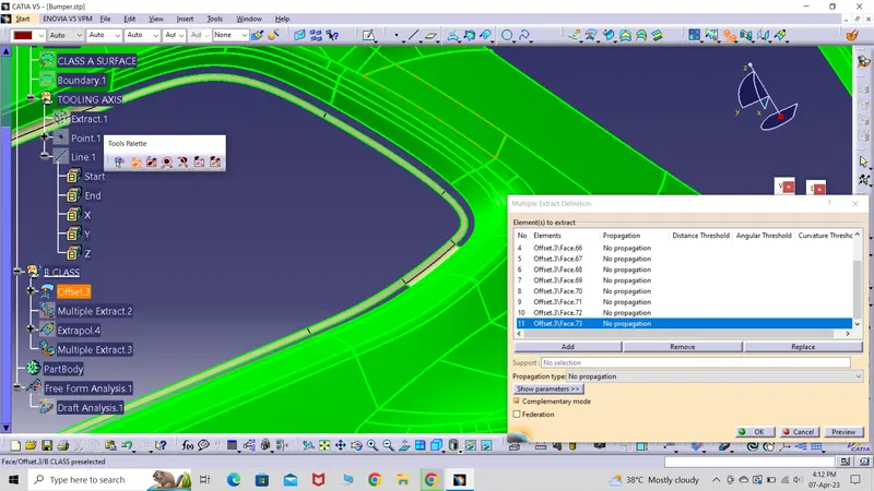
*) The boundary was created by choosing the limiting points.
*) The boundary had too many discontinuities and so curve smooth command was given to remove them.
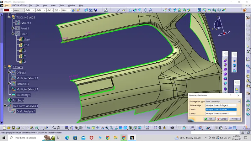
*) The boundary along with the surface was used to extrapolate so that the earlier surface and this particular surface intersect with each other.
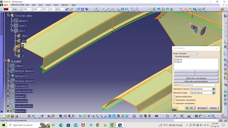
*) The two intersecting regions were then trimmed together to get the required surface of that region.
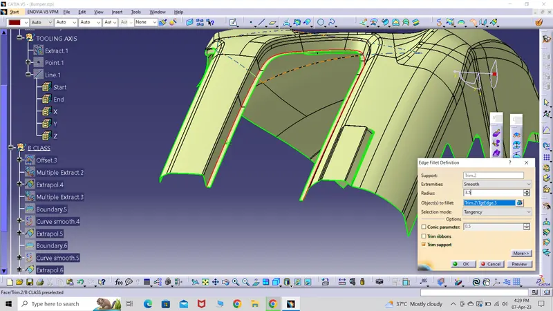
*) The edge was filleted by selecting edge fillet and the radius value was given as 3.5mm.
*) The same technique was used to extract the lower section of the bumper.
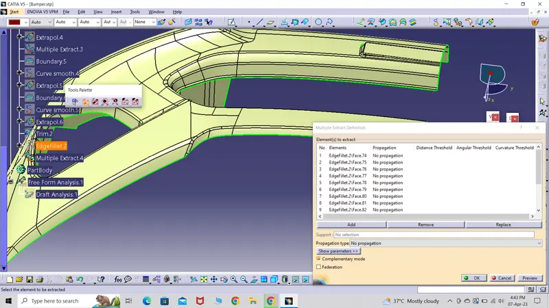
*) The lower flange was extrapolated to 3mm in length and would be later used for trimming with the other edge.
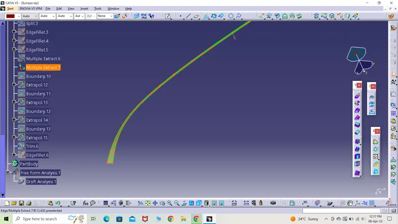
*) Extrapolation was carried out with multiple boundaries as the extrapolation was not executing with more than 1mm of length.
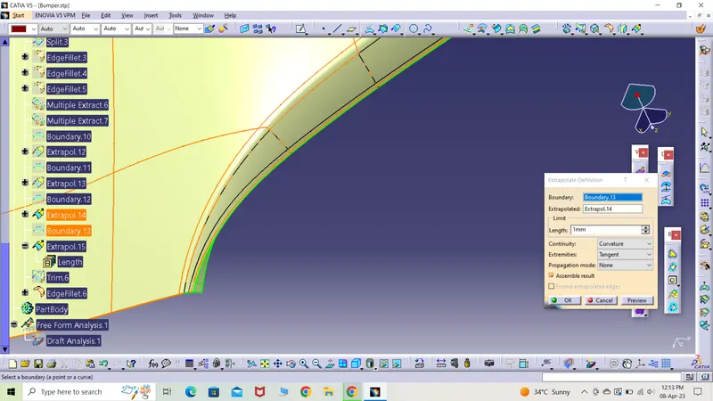
The two aforementioned edges were intersecting with each other and so they were made into a clean surface by trimming the extra length with trim command.
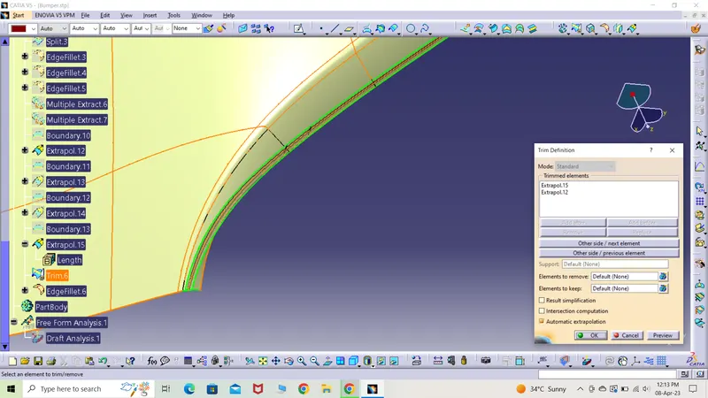
*) The last operation in this region was to give a fillet of 2mm on the edge just created in the above s.s.
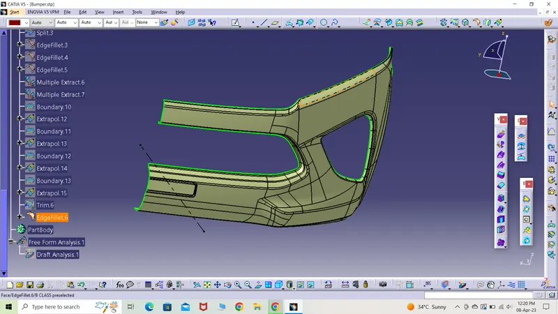
*) The next and final repairment was to create the number plate fillet so it was done with extracting the face method. All the walls and the base surface was extracted and later untrimmed.
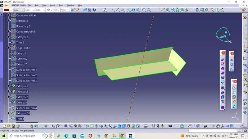
*) The surfaces were trimmed and later again trimmed with the main class B surface.
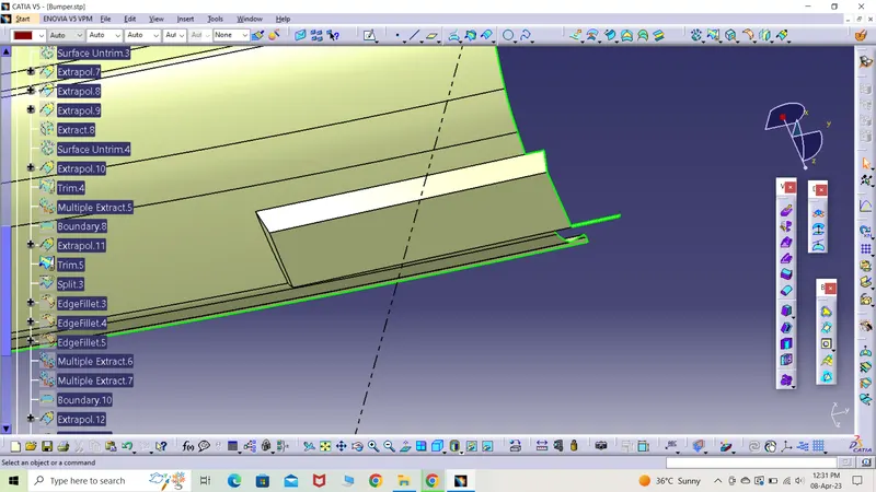
*) The extra unwanted portion was splited with the reference of zx-plane.
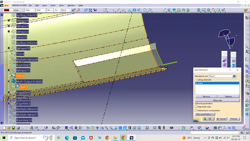
*) Catia was not displaying the radius of the fillet, so that particular region was extracted and then untrimmed.
*) It was still not displaying so a point was created on the extracted region and then an arc was created using three point technique.
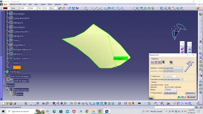
*) The class B surface of bumper was completed.
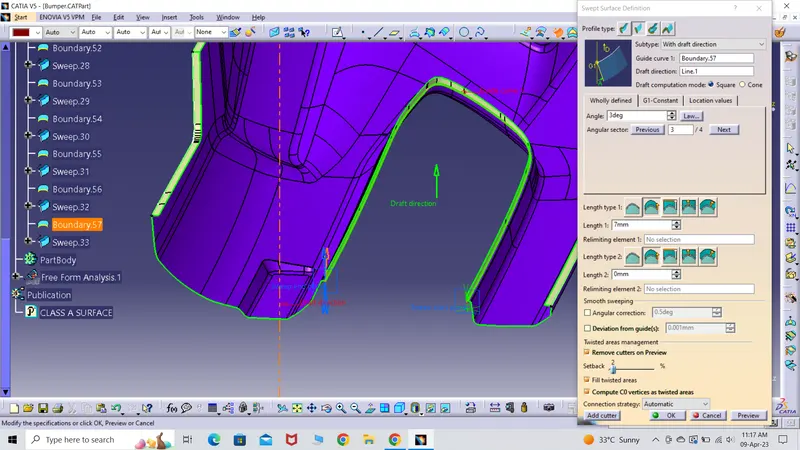
*) An new geometrical set was created with the name class C surface and all the operations that would be carried out to create C class.
*) Boundary was created on the specified region which would be later modified with swept command.
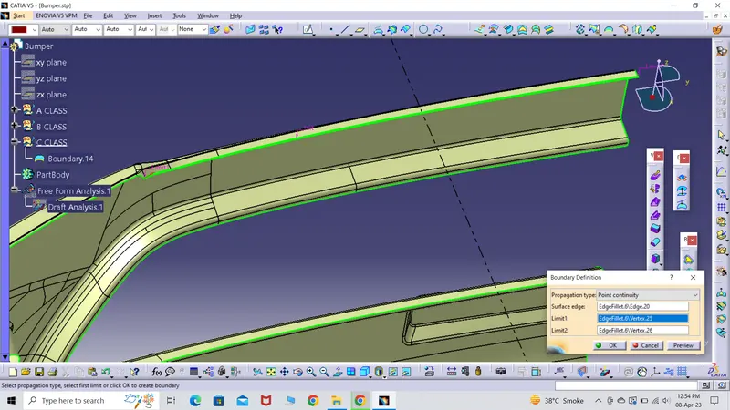
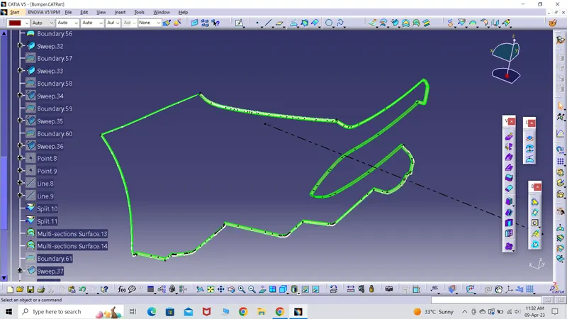
*) Some region were done by taking tooling draft direction and others by reference surface to create the surfaces.
*) Some edges were intersecting with the adjacent edge so a point was created on the two intersecting surfaces and later drawn a line through the same points.
*) The same line was used to split the surface so that the surfaces have some gap in between them.
*) The two adjacent surfaces then were then joined together by multi-section surface creation.
*) Surface A and C were joined together by using joint command.
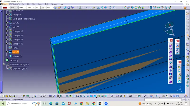
*) The surface that was joined was given a new color to avoid confusion. The same surface was tried to trim with class B surface but the command was showing an error.
*) To find out the problem, intersection was done on the model and there were some discontinuities shown by black dots.
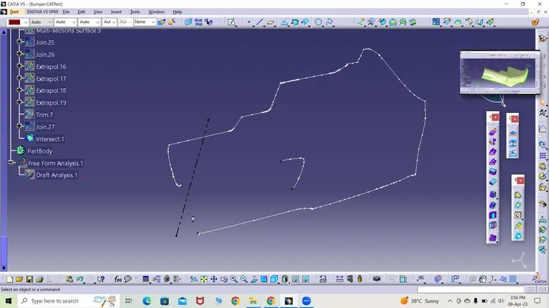
*) The gaps were resolved and again trim command was tried on the surface and it got executed.
*) The class C surface of the fod lamp duct was also created and joined with class A surface and then trimmed with clas B surface.
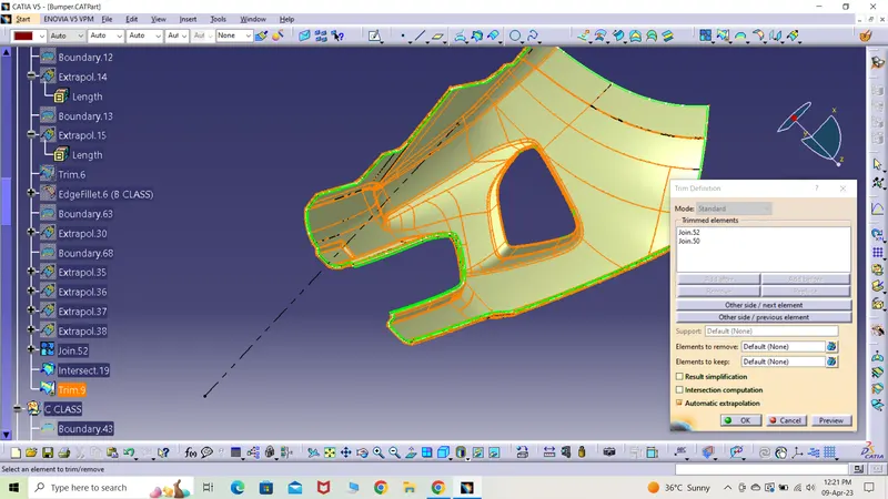
*) The final part was obtained and later the software was changed to part design mode where the same hollow part was converted into a solid part by using close surface command.
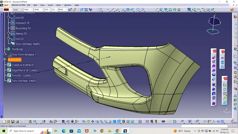
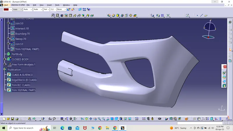
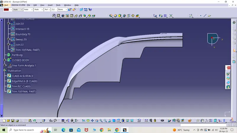
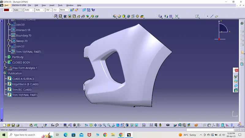
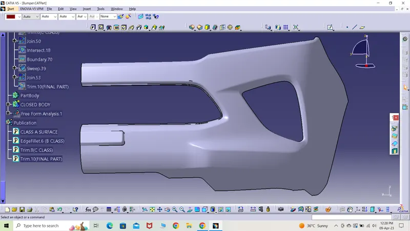
*) The solid part was obtained and is shown in different views.
ISOMETRIC VIEW
TOP VIEW
SIDE VIEW
FRONT VIEW
*) In the end, the draft analysis was done on the solid body and it was done by aligning the compass with the tooling axis. Then on a simple click on the part gave the result.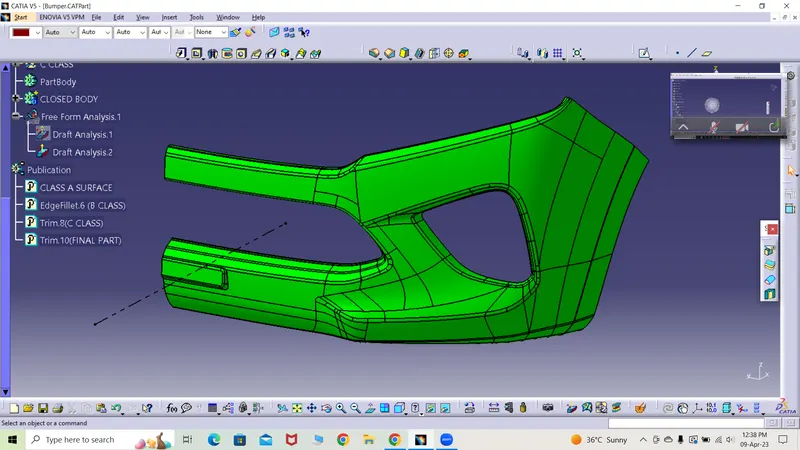
*) The part was good except the side wall as it was showing with a blue colour.
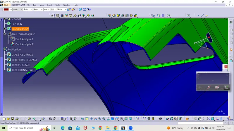
*) The angle was given as neutral i.e 90 degree so it was changed to 93 degrees and again draft analysis was carried out and this time it was passed and toolable and producible.