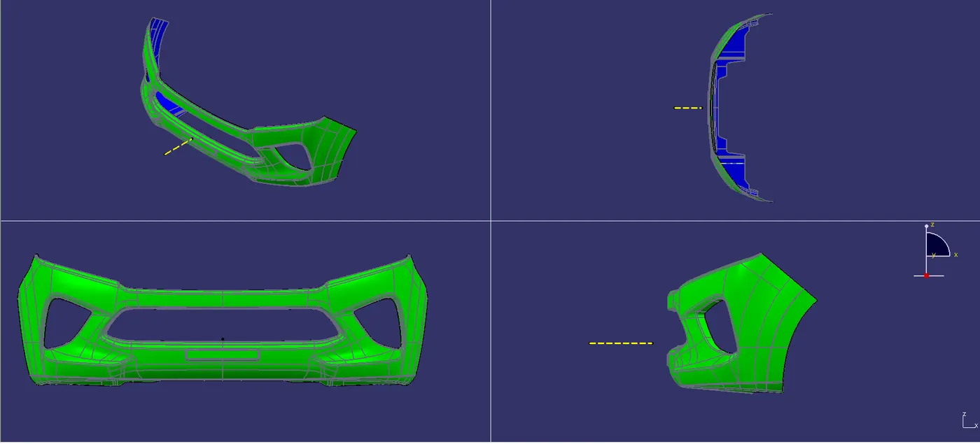
Week 9 - Challenge 3 - Bumper
Aim:
To Create a solid of FR-Bumper part with the A - Surface given as input by considering all the manufacturing requirements.
Design Considerations:
Bumper is a symmetric part from the car 0. i.e., LH and RH are same.
- Nominal wall thickness =3mm
- Nominal Draft angle= 3 °
Class A - Surface Inspection:
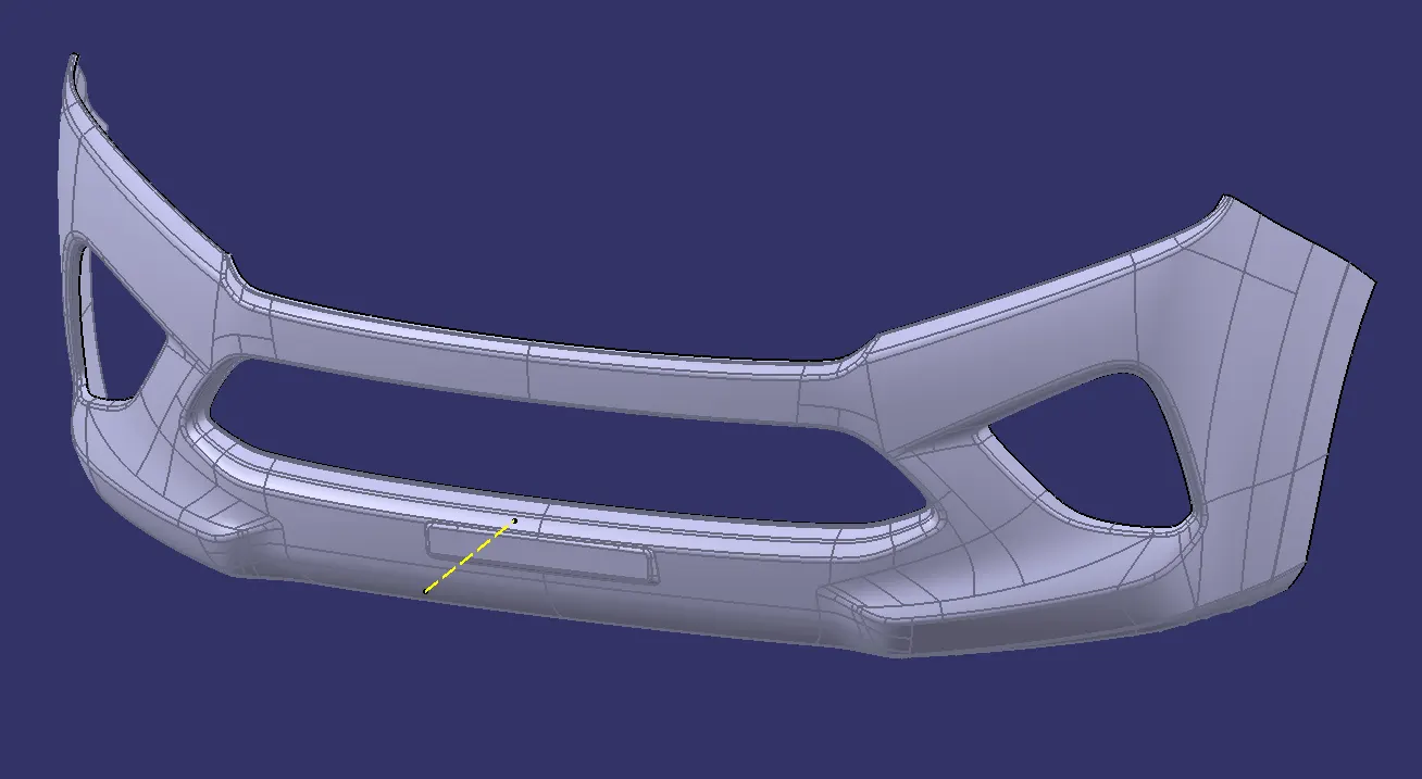
- The given A -Surface is first checked for any patch connectivity errors visually and by using boundary command.
- Any Changes required in patching is intimated to the styling team.
- The surface has two or more internal hard edges, and this due to the patch join quality.
- The concern is highlighted to the styling team and permission is obtained to fix this issue, and fixes are carried out.
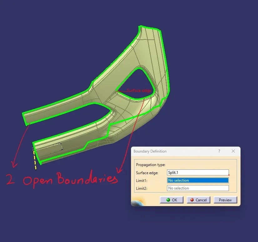
.
Tooling Axis and Draft analysis:
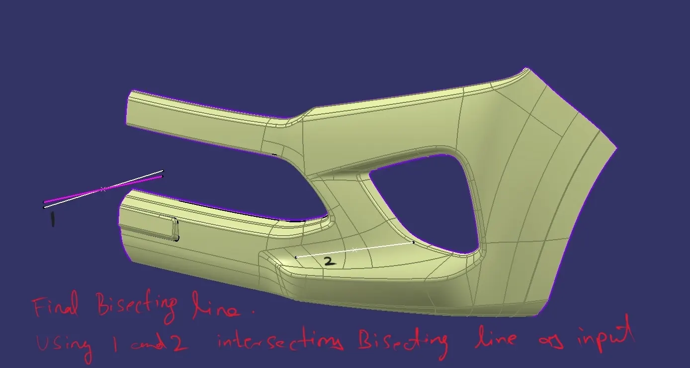
- As bumper is a part that runs through all the width of a car the surfaces can be of variable draft and changes along the width of the car from the car’s 0 on either side, so intersections are taken along the ZX-Plane in two arbitrary regions one at car’s Y = 0mm and Y = 700mm on the LH side and lines are created.
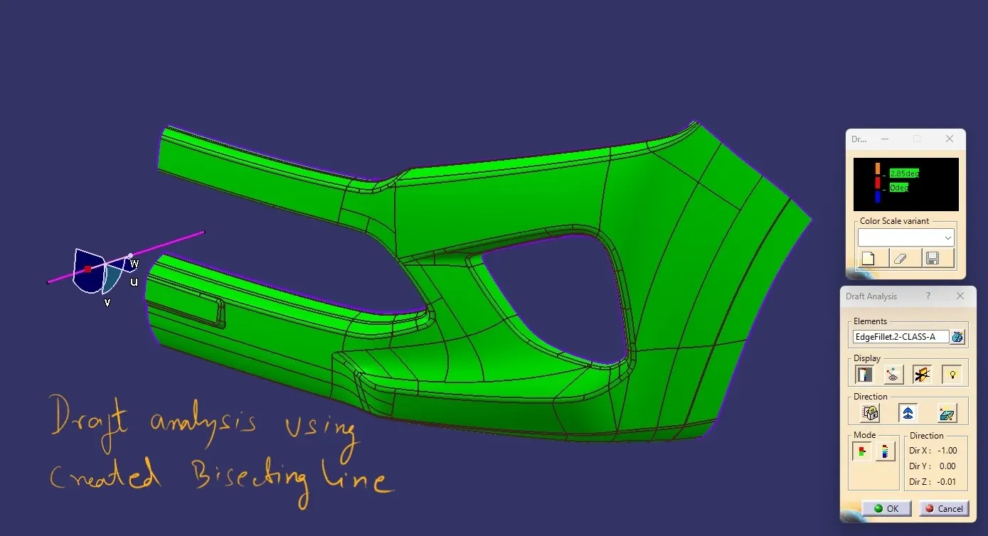
- Then two bisecting lines are created on these two intersections and a bisecting line is created from the two bisecting lines, a draft analysis is performed.
- If the A - Surface is clearing the draft of minimum 3 then the tooling axis is fixed, or necessary modifications are carried out to clear the draft.
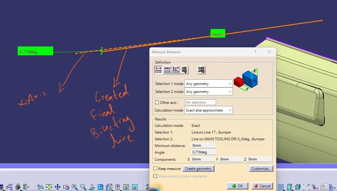
- Since the line created is just 0.8° from the X-axis the X-axis is itself taken as the tooling axis and the analysis is performed again.
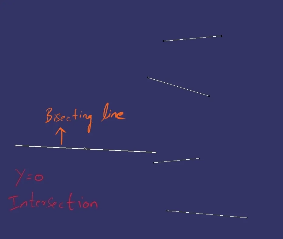
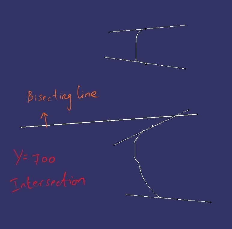
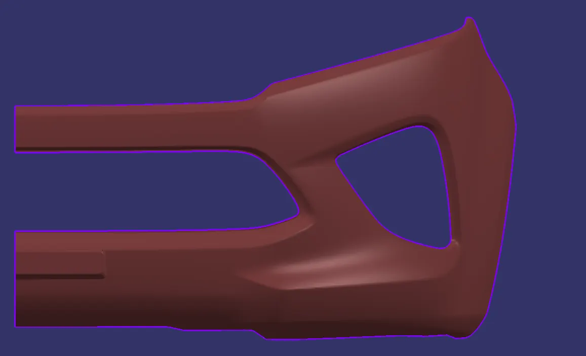
CLASS - A SURFACE WITHOUT HARD EDGES |
|---|

B - Surface Creation:
Given that the A - Surface clears the draft, B- Surface is created by offsetting the A - Surface by the nominal wall thickness, which is 3 mm here. As this part is symmetric along the width of the car on both sides from the center and also a bigger part, offsetting patch by patch is a time-consuming process. So, it is offsetted overall.
There are some patches which would not offset and throw errors, accept the offset without the patches and remove the bad surfaces using join command with sub-elements to remove.
Then the fillets are given accordingly so that even thickness is maintained throughout the offset.
Internal hard edges if any are removed using the join command with sub-elements to remove and creating new patches.
C - Surface Creation:
- The C- Surface is created using the boundary of the A-Surface.
- The C-Surface is of two types which depends on the boundary of the A-Surface and its Surface nature of alignment with the tooling axis.
- If the Surface is perpendicular to the tooling axis, then the boundary is visible to the tooling axis. Here, there are two possibilities one is an opening draft or a closing draft which is dependent on the parting line placement. If an opening draft is given then the parting line will be placed on the B- side of the part, on the other hand the parting line is on the A-Side of the part, when a closing draft is given.
- This is important as the parting line defines the opening and closing of the mold halves and a molding defect called flash, where some material tends to escape at the parting line area from the mold.
- The other case, if the A -surface is itself parallel to the tooling direction then the boundary is kind of hidden from the tooling direction view by the A-surface itself, in this Case the C-Surface is created perpendicular to the A-Surface.
Close Surface and Body Creation:
The C-Surface is joined with the A-Surface and then trimmed with the B-Surface. Then it is checked for any open patches using the boundary Command if the command fails, then the surface is closed perfectly.
Then the closed surface is made to a solid by using close Surface command.
Draft analysis:
The closed body is subjected to a draft analysis.