Week 9 - Challenge 3 - Bumper
BUMPER CHALLENGE
AIM- Create plastic bumper component through the given Class A surface & perform draft analysis on the plastic component.
[NOTE: FOLDER FILE NAME- OPEN THE BUMPER PART FILE]
OBJECTIVES
Create Tooling Axis
Create Class B & C surface
Create close Surface
Perform Draft Analysis
SPECIFICATION
Bumper Thickness = 3mm
Minimum Draft angle= 3 degree
INTRODUCTION
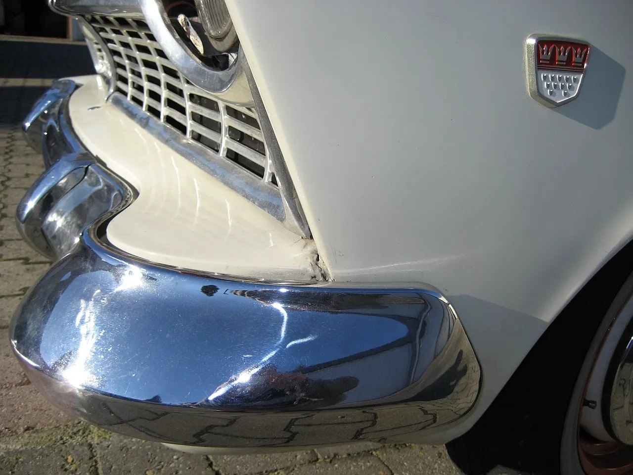
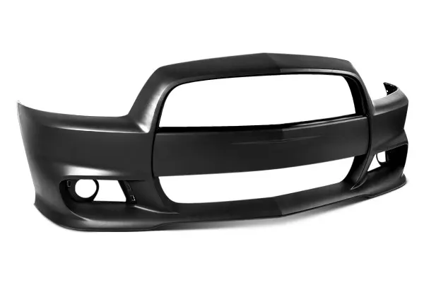
A bumper is an overhanging structure attached or integrated with front & rear end of the automobile to absorb impact of the collision & reduce the major internal damage components which ideally minimize the repairing costs.
A bumper is an overhanging structure attached or integrated with front & rear end of the automobile to absorb impact of the collision & reduce the major internal damage components which ideally minimize the repairing costs.
Mainly automobile bumper was created in early 1900’s which consist of metal beams cooperated at front & rear end. It was designed to protect expensive & fragile components like cooling systems, front & rear lighting systems, hood & exhaust. As years of technology is evolving to modernity the material also shifting to fibre material like polycarbonate (PC) & Acrylonitrile Butadiene Styrene (ABS). Some of the high-performance automobile manufacturers are using Carbon-fibre materials in vehicle bumper for the vehicle light weight.
DESIGN METHODOLOGY
· Skin data aka Class A surface will be provided by styling team.
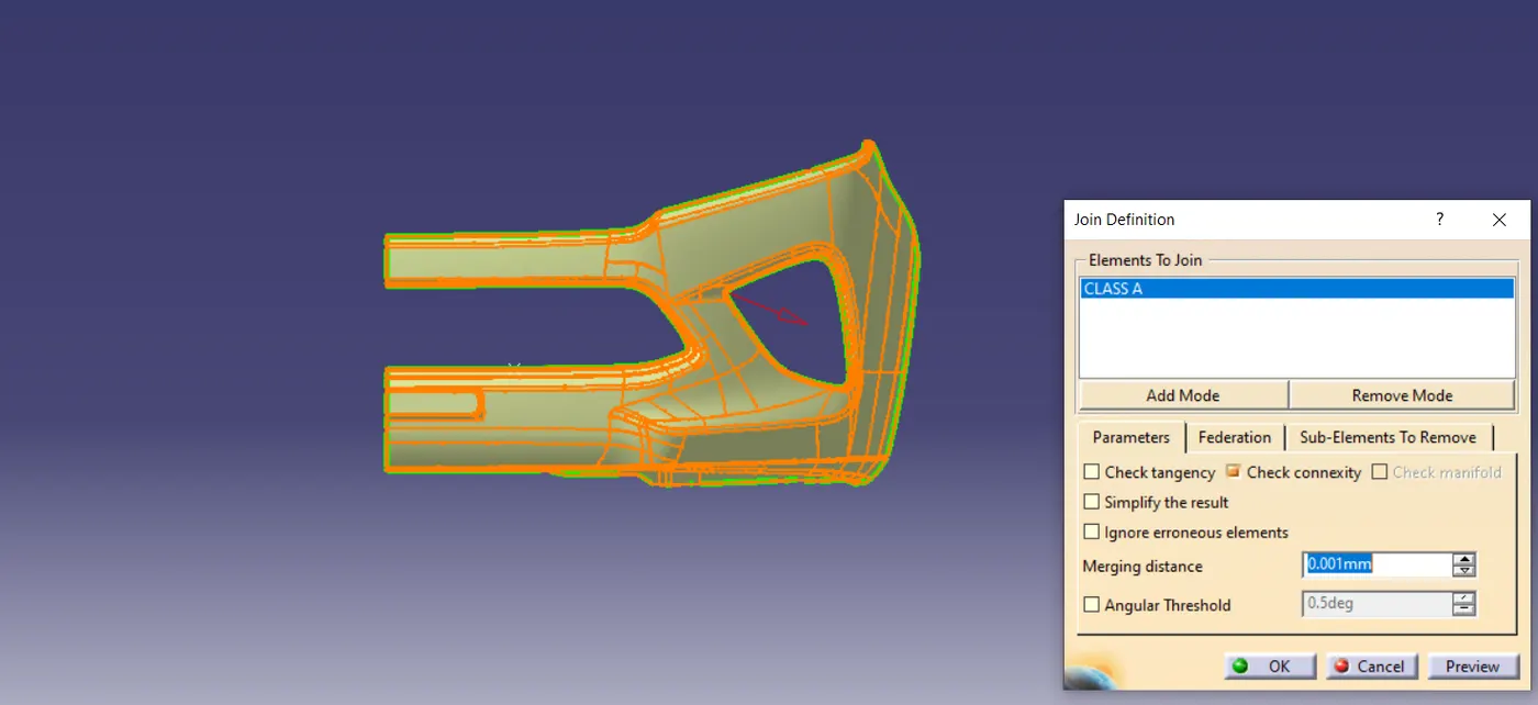
· First for checking the Class A surface for any gaps, we can check through Join Command or boundary command. If it shows one continuous outline border around the Class A surface, it means there is no gap in A surface & we are good to go for further operation to make a proper bumper structure.
· TOOLING AXIS- The direction in which the Mold or core & cavity opens is the tooling axis.
First, we have to cross-check with the three directional axis x-axis, y-axis & z-axis which is suitable to manufacture the part. In this case, x-axis is the suitable tooling axis direction for the bumper class A surface. Select a mid-point from point command in Class A surface. Through line command, select point-direction option & select the point which it has been created & give x-direction elongation.
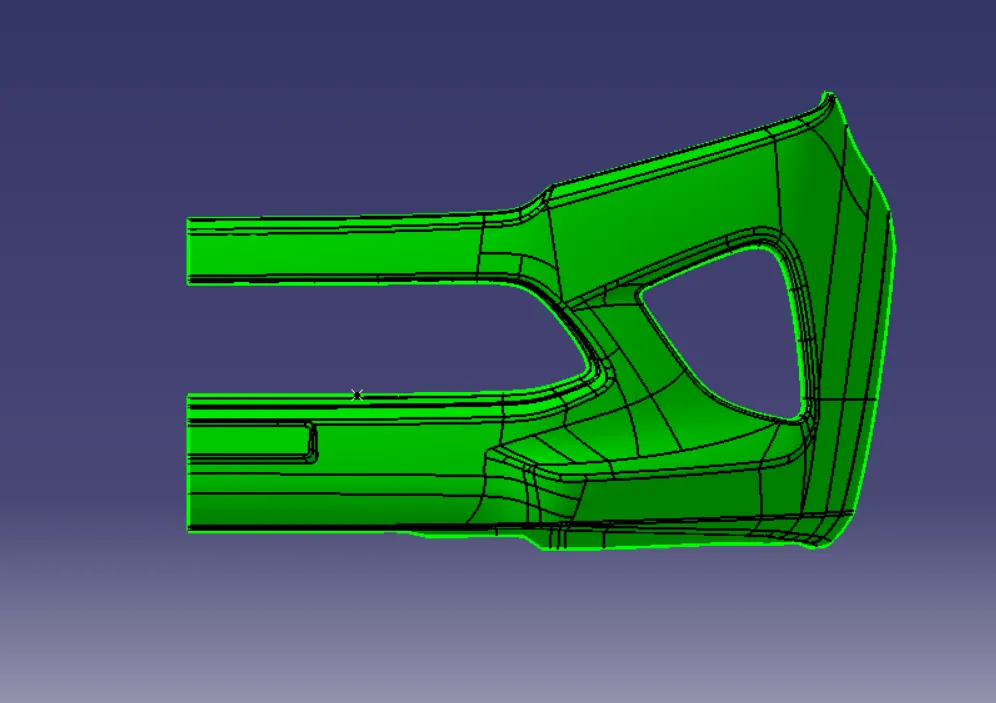
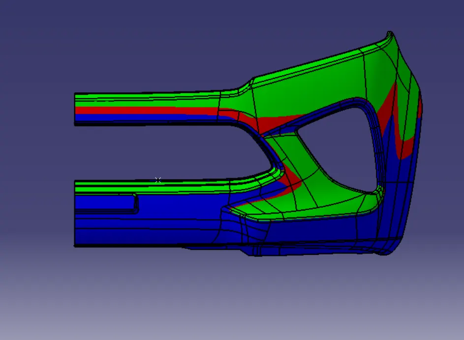
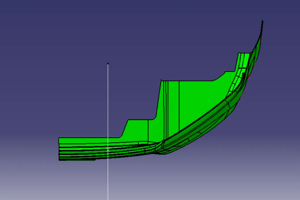
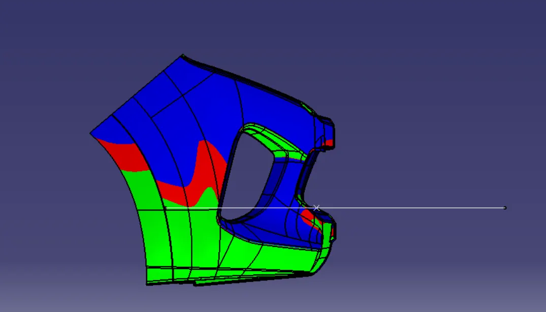
· DRAFT ANALYSIS OF CLASS A SURFACE- Draft analysis is a command which enable to detect the draft angle of the surface. This type of analysis is performed on the colour ranges to identify the zones on the analysis of the element with references to tooling axis.
Draft analysis on plastic material is checked with reference to tooling axis at minimum angle of 3 degree & showing green colour then it is safe.
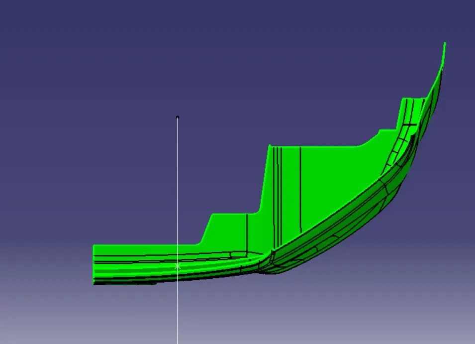
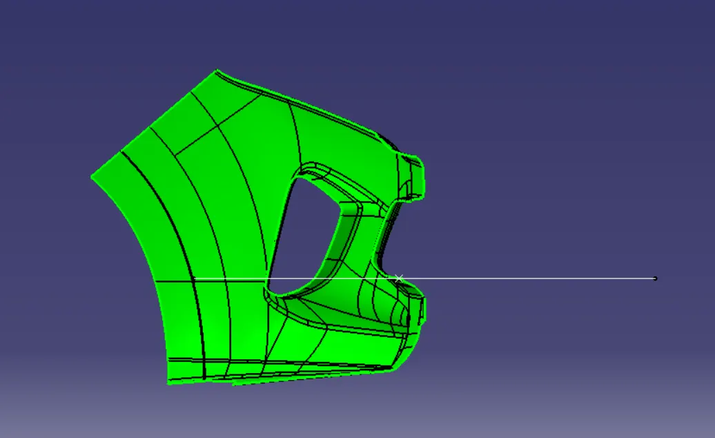
· CLASS B SURFACE CREATION- A surface below the Class A surface is created by design engineer to give a desirable thickness. This surface is also known as engineering surface.
First, step is offset the Class A surface to 3mm inward direction. Class B surface is created. We noticed in Class B surface there are unfinished patches while offsetting the surface.
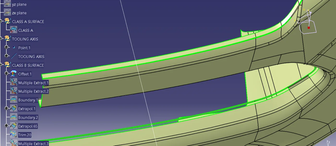
So, one by one we will we work on the unfinished patches in the Class B surface & fix it. By selecting the extract command & boundary command, we will make boundary line & extrapolate the surface & later trim the extrapolate surface we have created will generate good surface. Measure & calculate the fillet surface to create on the Class B surface in the cornering section. So, Creation of the Class B surface is done.
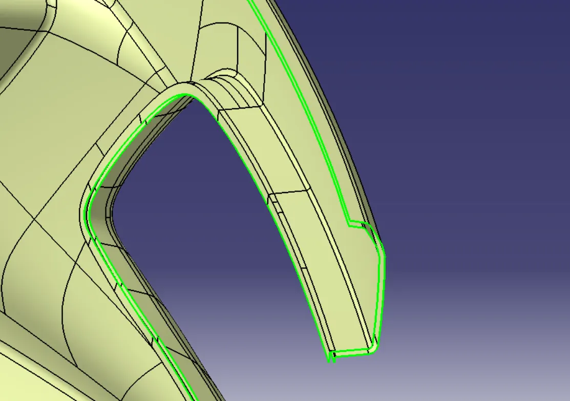
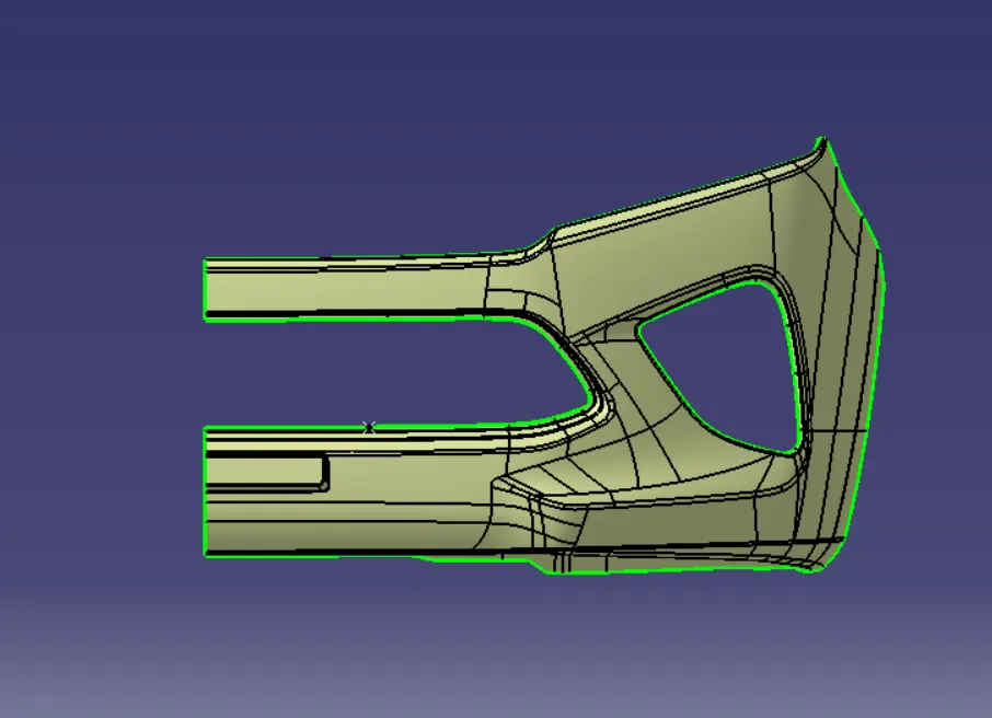
· CLASS C SURFACE- A surface that join Class A Surface & Class B surface.
Since it is a complex Class A surface, we cannot simply create the Class A surface boundary curve in one go & by sweep command create Class C surface. We create boundary in the grill portion, fog lap portion & whole bumper with sweep command & also need to extrapolate the surface & trim the unwanted portion of the surface. Join the Class A surface, Class C surface & Class B surface by joining command. Check with boundary command to check it is closed object.
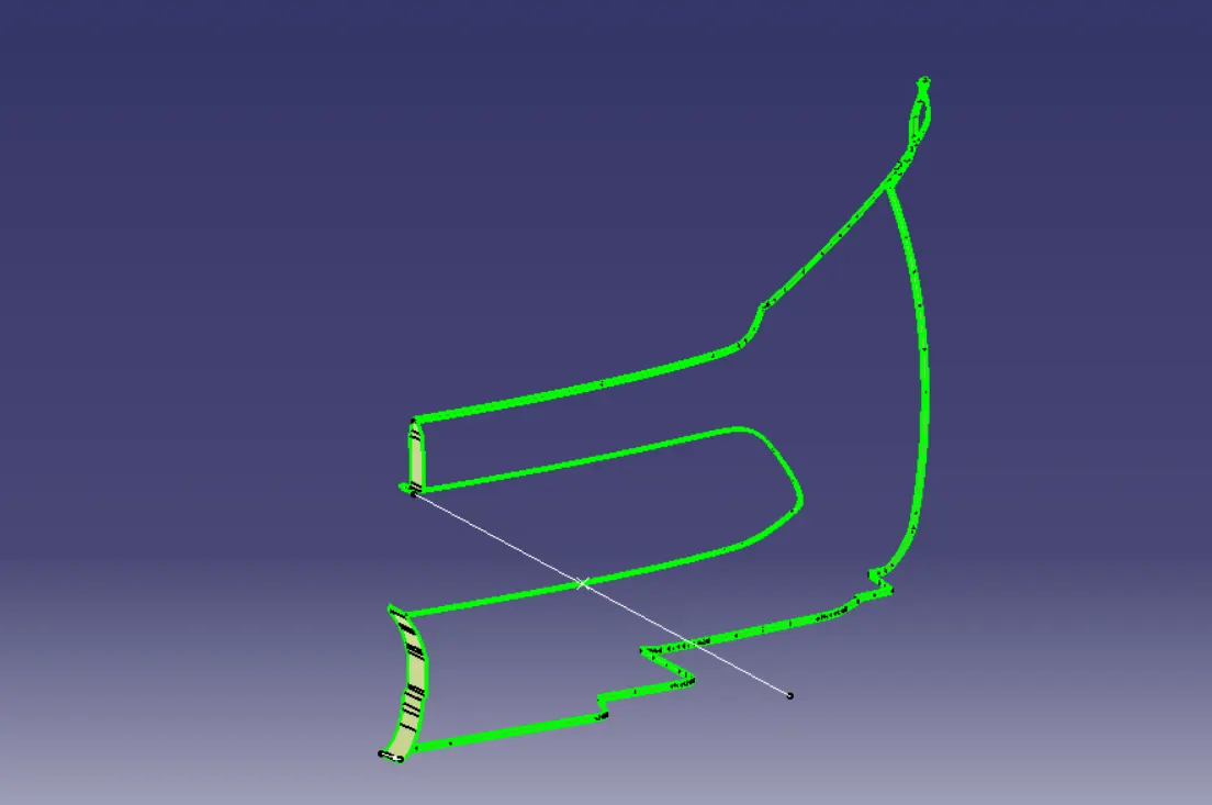
At last step, define to part body & switch to mechanical design mode to made the body solid part by going to closed surface.
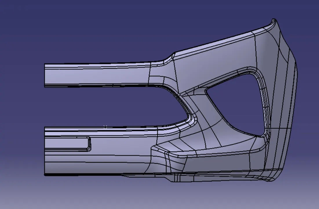
Hence, the final surface is created.
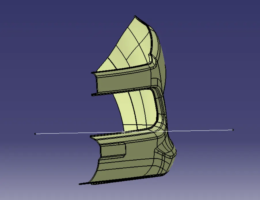
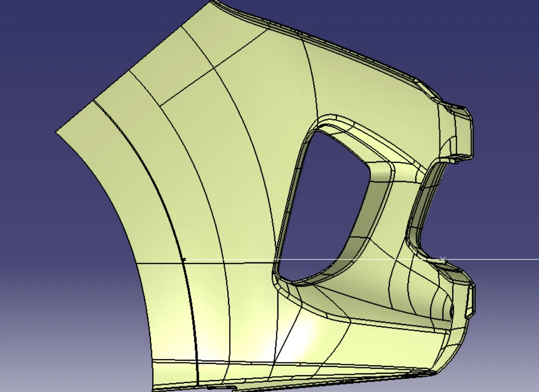
CLOSED SURFACE
DRAFT ANALYSIS OF CLOSED SURFACE
CONCLUSION- I have successfully create Class B & Class C surface of the bumper by using the given Class A surface along the tooling axis.