Week 9 - Challenge 3 - Bumper
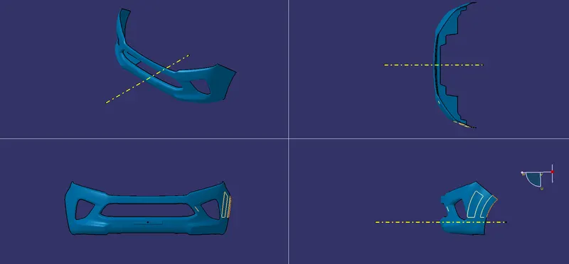
AIM: The objective of this project
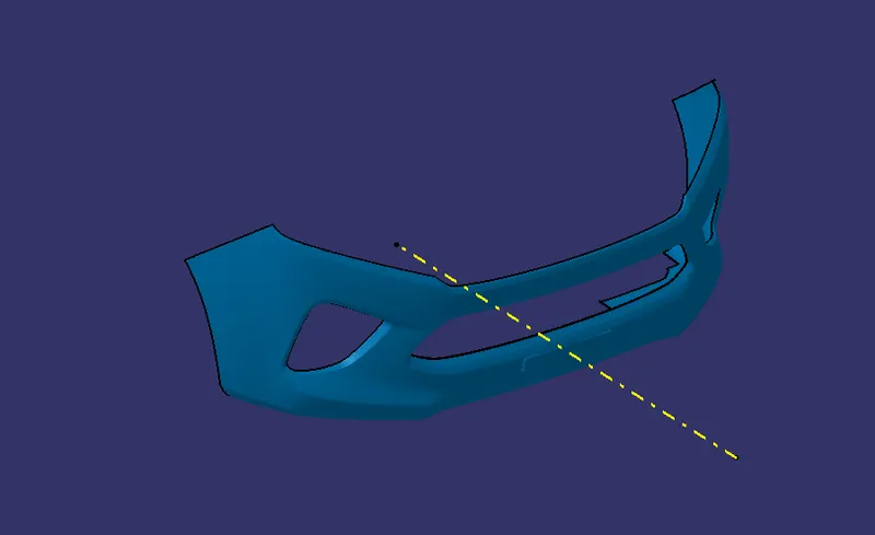
- To create the Bumper Plastic component through the given Class-A surface.
- To create a Tooling Axis for the Class-A Surface should be created meeting the requirements of the draft angle
- To perform the the Draft analysis on the final closed model.
STEP 1
CLASS A SURFACE
- To begin with, import the input surface and join all the surfaces using Join feature.
- Check for any black line for repair work by selecting the "shading with edges without smooth edges", if so do the repair work on those lines.
- First, extract the surfaces which needs repair work and use extrapolate feature to extand the surface. And use trim option to cut the unwanted surface .
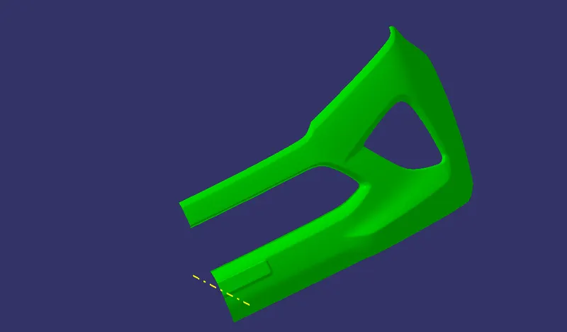
- Finally give the edge fillet of about 0.25 mm or 0.5 mm on the sharp edges. Now, join those extracted surface with edge filet to the joined input surface to get the final class A surface.

- Class A surfrace with repair work
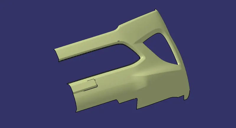
- Final class A surface
STEP 2
TOOLING AXIS CREATION
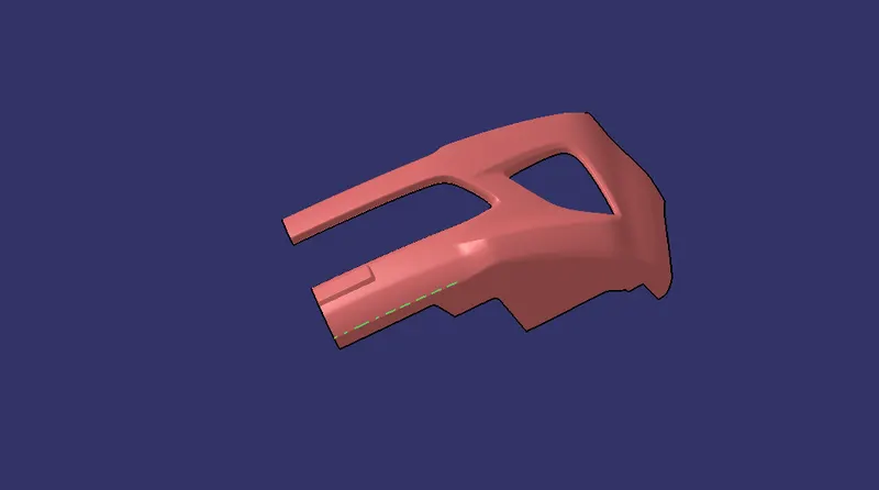
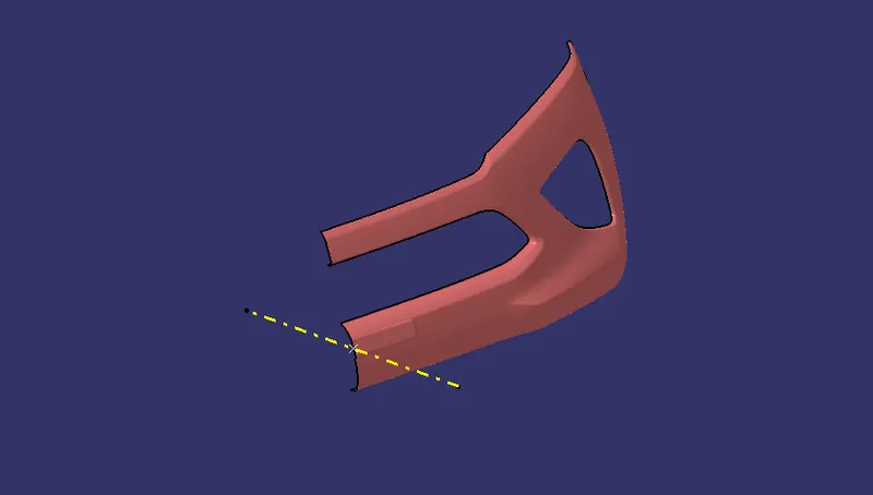
- First, create a point on the class A any Flat surface and create a line with respect to that point and the respective direction.
- Then, change the line style for better look.
STEP 3
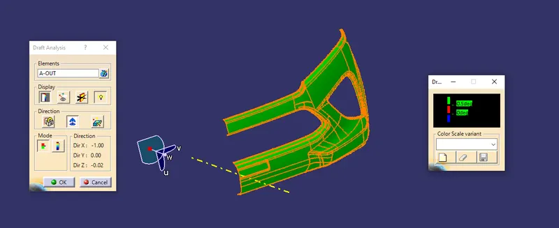
DRAFT ANALYSIS ON CLASS A SURFACE
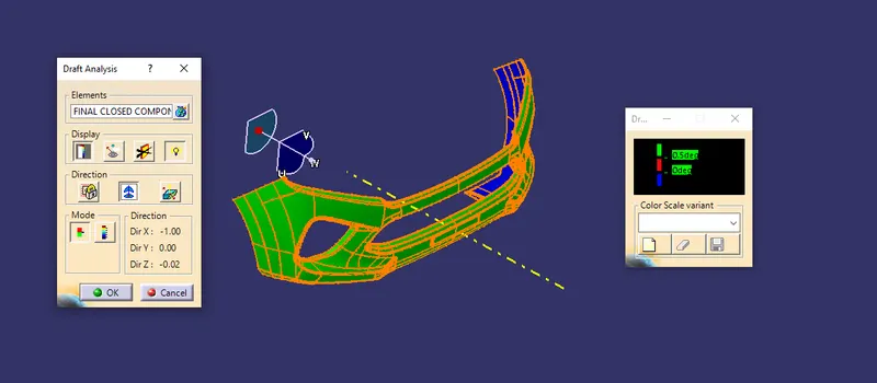
- Select the Feature draft analysis and align the compass with respect to the tooling axis and select the class A surface as the element and click Ok to see the anlysis.
STEP 4
CLASS B SURFACE
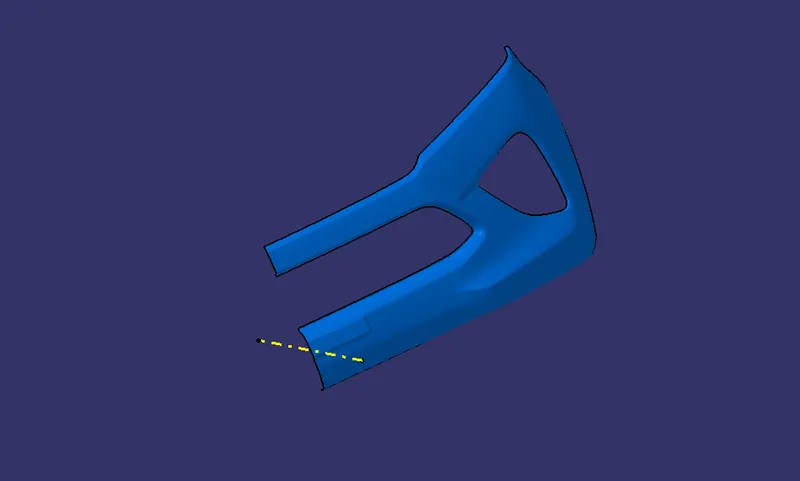
- Now, offset the class A surface to about 2.5 mm using offset command. Then select "shading with edges without smooth edges" for checking any black lines for repair work. If there are any lines like that, use the same method mentioned in the repairing of the class A surface.
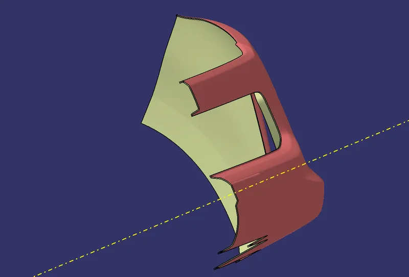
- Class B surfcae with repair work.
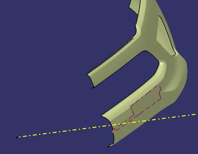
- Final class B surface
STEP 5
CLASS C SURFACE
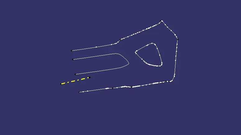
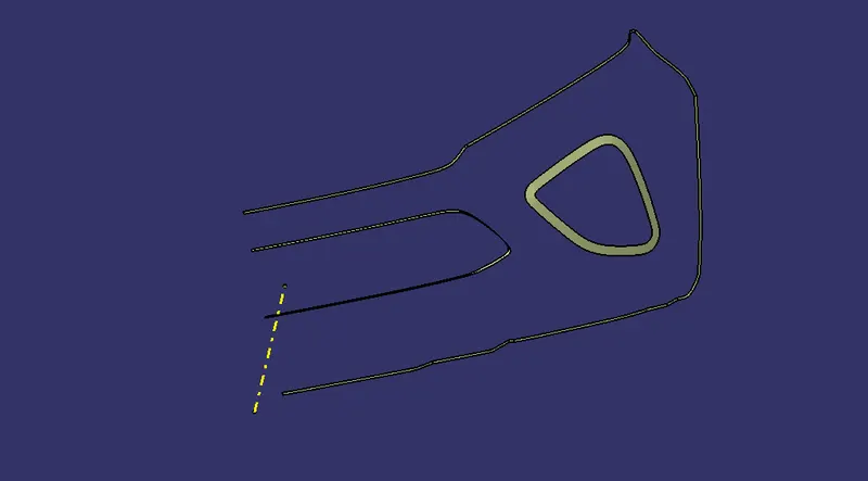
- Create a boundary on the class A surface and use curve smooth option on that boundary and use sweep option with reference with surface method.
- Otherwise use boundaryseperately on the class A surface and use sweep option with reference to surface or with draft angle method for respective sides for sweeping.
- The draft angle given was about 3 degree or 87 degree respectively.
- After sweeping all the surface, use trim to cuit out the extra surface and join all with the join feature.
STEP 6
CLOSED SURFACE
- Now, join the class A surface with the class C sweeped surface.
- Then use trim option to trim the joined surface with the class B surface for optaining the final closed surface.
- Finally, use symmetry optioin to mirror the 1st half of the closed surface bumper and join both sides using Join feature with merging distance 0.1 mm.
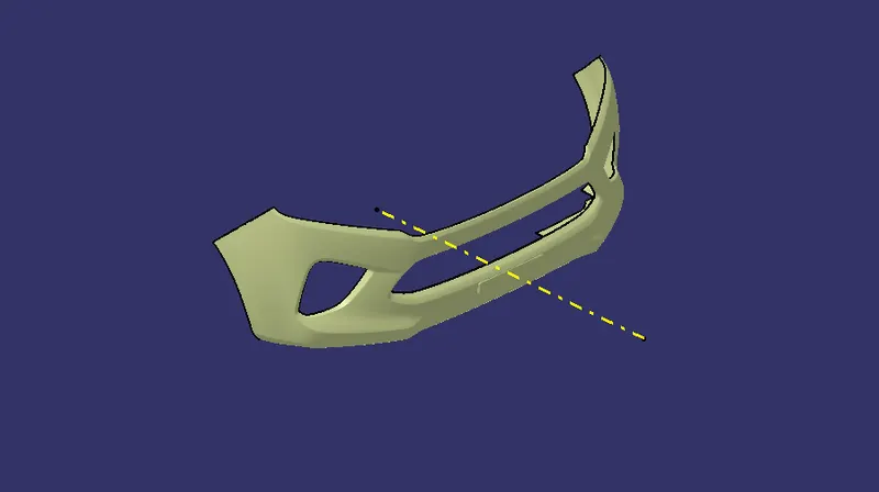
SOLID COMPONENT
- Apply the close surface option on the closed bumper surface for making it solid compoent.
STEP 7
DRAFT ANALYSIS ON FINAL CLOSED SURFACE
- Now, select the Feature draft analysis and align the compass with respect to the tooling axis.
- Select the final closed surface as the element and click Ok to see the anlysis.
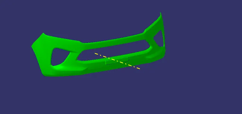
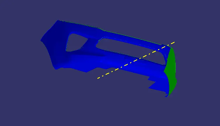
- MULTI VIEW