Week 9 - Challenge 3 - Bumper
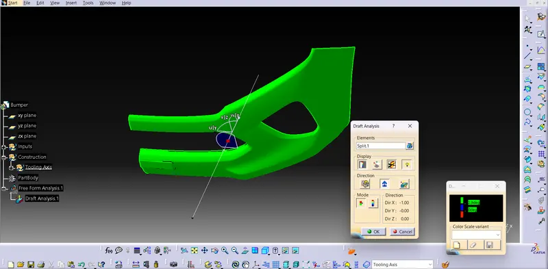
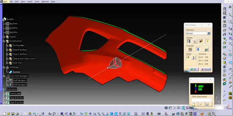
The given class A surface was analysed and since most of the surface area was visible when viewed along x-axis, it was clear that x-direction is the appropriate direction for tooling. To locate the tooling axis, a point was created on an edge of the bumper surface. Then a line was created along x-axis, through the point. Then the draft analysis was performed on the part with the line as tooling axis, and it was found that all the faces of the surface cleared the draft analysis. Hence the same line has been considered as the tooling axis.
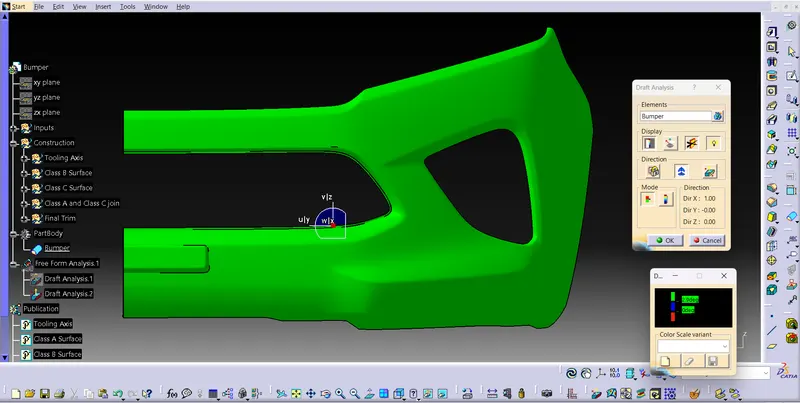
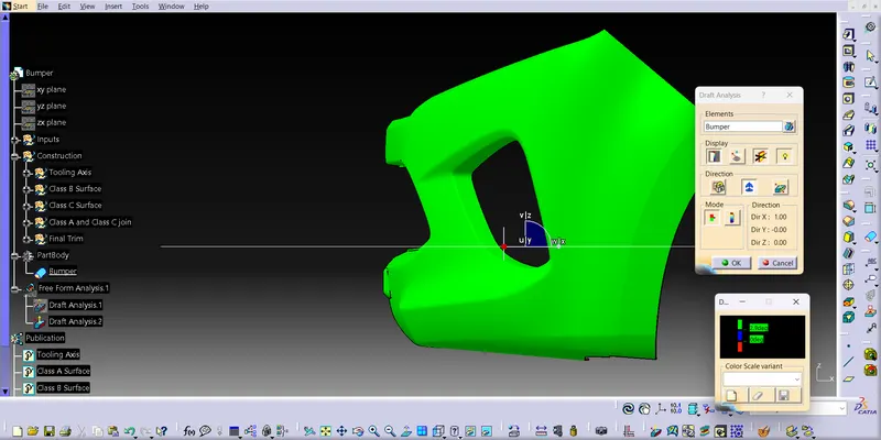
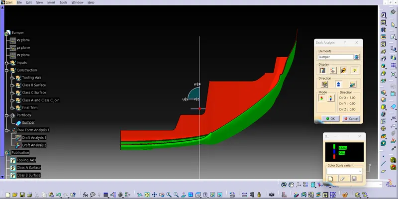
Once the part has been created, the draft analysis was performed on it with the tooling axis as the draft direction. The compass was aligned on to the tooling axis, and both the class A surface and the class B surface cleared the draft analysis. The respective images have been attached below.