Week 10 - Challenge 1- Attachment Feature Creation (Ribs & Screw Boss)
The given class B surface was analyzed. From the given surface, it was clear that y-axis is the suitable tooling direction for the component. A plane was created approximately in the middle of the surface with xy plane as reference. An intersect of the given surface was taken along this plane. The lines representing the walls of the surface were extended and a bisecting line(dummy tooling axis) was created. Then another plane was created approximately at 70mm from the yz plane and another intersect of the given surface was taken along this plane. Using the same method, another dummy tooling axis was created. Then the main tooling axis was created by bisecting these two dummy tooling axes.
To create the class A surface, the given class B surface was ofset outwards, the thickness of the part was not mentioned, so it was assumed to be 2.5mm. Then the class C surface was created, joined with class A surface and trimmed withe the extrapolated class B surface. Hence the component was created.
The ribs were created as per the instructions in the video. Since the exact locations of the ribs were not provided, they were assumed. Rib thickness was taken as 1mm(2.5*40%) with height as 12.5mm. For screw bosses, diameter was taken as 2.5 since height to diameter ratio and the height to base thickness ratio were same in the diagram given in the question. Both the ribs and the screw bosses were drafted for 0.5 degrees on all the necessary sides and filleted for 0.25mm radius.
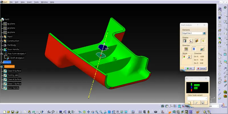
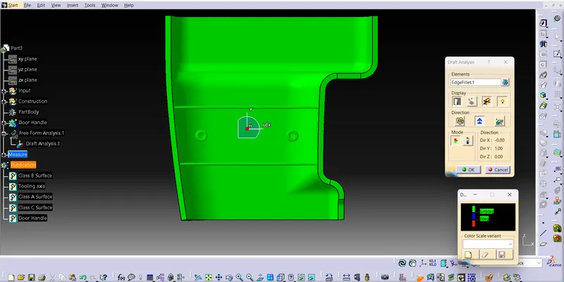
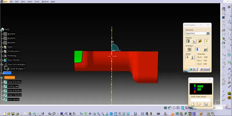
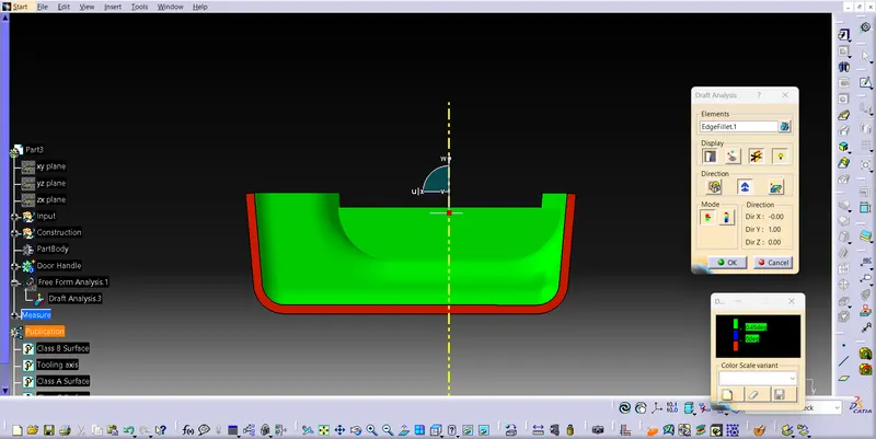
The draft analysis was performed on the final component with the tooling axis as the draft direction. The compass was aligned on to the tooling axis, and all the ribs and the screw bosses cleared the draft analysis. The respective images have been attached below.